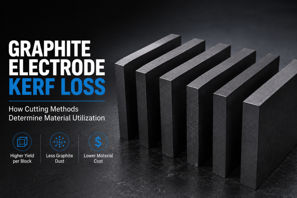
Graphite electrode kerf loss is the volume of isostatic graphite permanently converted to fine dust during each cutting pass through a billet. In EDM electrode manufacturing, even a few extra millimeters of kerf width per cut compounds across dozens of slices — reducing the number of usable electrode blanks extracted from each block and increasing the true cost per electrode before any machining begins.
What Is Graphite Electrode Kerf Loss?
Graphite electrode kerf loss is the width of material permanently removed by the cutting tool or wire as it passes through a graphite billet. It equals the diameter of the cutting medium — saw blade, milling cutter, or diamond wire — plus any lateral clearance required for the tool to move freely through the cut.
En EDM graphite electrode manufacturing, the cutting stage divides raw billets into electrode blanks before final shaping. Every millimeter of kerf at this stage exits the process as unrecoverable graphite dust rather than a usable part. That distinction matters most when the material being cut is EDM-grade isostatic graphite — a precision-engineered product manufactured under high isostatic pressure to achieve uniform grain structure, low porosity, and consistent density throughout the block.
The four variables that define total kerf loss in any electrode cutting operation:
- Kerf width per cut — determined by the cutting tool or wire diameter plus abrasive protrusion
- Number of cuts per billet — determined by blank thickness and billet dimensions
- Material grade — denser, finer-grain grades generate finer kerf particles with less edge breakout
- Cutting direction — cross-grain vs. with-grain orientation affects how cleanly graphite fractures at the kerf edge
Together, these variables determine how much of each billet becomes finished blanks versus manufacturing waste.
Graphite Electrode Kerf Loss Across Cutting Methods
The choice of cutting method is the single largest controllable factor in graphite electrode kerf loss. Different approaches impose fundamentally different kerf widths, and those differences compound when multiplied across the many cuts needed to fully slice a production billet.
| Método de corte | Typical Kerf Width | Surface Quality After Cut | Graphite Dust Level |
|---|---|---|---|
| CNC Milling (roughing pass) | 6–12 mm | Requires heavy finishing | High — open process |
| Circular / Carbide Saw | 2–4 mm | Moderate; chipping at edges | Alta |
| Sierra de cinta | 1.5–3 mm | Moderate; dressing passes needed | Moderado a alto |
| Sierra de hilo diamantado | 0.2–0.5 mm | Near-net-shape; minimal finishing | Low — enclosed cutting zone |
Kerf width ranges based on typical tool geometries for each method as documented in precision graphite cutting equipment specifications.
Como un comparison of graphite electrode cutting vs. machining methods shows, the wire saw’s narrow kerf is not only a material efficiency advantage — the cleaner cut surface also reduces the amount of secondary finishing required before the blank enters final electrode shaping. The electrode blank emerges closer to its target geometry, with less surface damage to remove in the next step.
For a production run requiring 20 electrode blanks from a single billet with 19 cuts needed, the gap between a 2.5 mm band saw kerf and a 0.35 mm diamond wire kerf represents 19 × 2.15 mm = approximately 41 mm of additional material consumed by kerf alone — material that could otherwise contribute to one or two additional blanks per billet.
Why Graphite Electrode Kerf Loss Amplifies Material Costs
The financial impact of kerf loss depends directly on the grade of graphite being processed. EDM-grade isostatic graphite — the material required for precision die-sinking electrodes — is not commodity graphite. It is produced through a controlled manufacturing process involving isostatic pressing at high pressures, followed by extended thermal treatment, to achieve the grain uniformity and density that EDM applications require.
Manufacturers such as SGL Carbon (SIGRAFINE® grades) y Toyo Tanso (TTK series) produce these materials to tight specifications precisely because the performance of the finished electrode depends on material consistency throughout the blank — not just at the surface.
This creates a kerf loss amplification effect that operates on two levels:
Direct material loss: Each gram removed as kerf dust is precision-manufactured material that exits the process with zero recoverable value. In isostatic graphite, the material removed by the kerf is the same high-grade material as the finished electrode — not a lower-grade skin or external layer.
Yield compression per billet: If a billet produces 18 usable blanks using a narrow-kerf cutting method but only 15 blanks using a wide-kerf method, the per-blank material cost increases by 20% even though the raw billet cost is identical. At higher production volumes, this compression in yield per billet has a direct effect on production economics that purchasing alone cannot offset.
The practical framing: reducing graphite electrode kerf loss is not primarily a waste management initiative. It is a yield optimization that determines how many usable electrode blanks can be extracted from each unit of raw material — before any machining labor is applied.
How Diamond Wire Cutting Controls Graphite Electrode Kerf Loss
Diamond wire saw technology achieves narrow, consistent kerf in graphite by replacing wide mechanical tooling with a continuous steel wire embedded with diamond abrasive. As the wire traverses the graphite at high speed, it abrades a path equal to the wire diameter plus the protrusion of the bonded diamond grits — producing kerf widths well below 0.5 mm for wires in typical production diameter ranges.
Three parameters directly control kerf loss in diamond wire graphite cutting:
Wire diameter: Thinner wire produces narrower kerf but must operate at reduced tension and lower feed rates to avoid breakage. The appropriate wire gauge depends on billet height, required surface quality, and production throughput targets.
Abrasive bonding and distribution: The method by which diamond particles are bonded to the wire determines how consistently the abrasive protrudes from the wire surface. Resin-bonded and electroplated diamond wires produce more uniform and predictable kerf widths compared to loose abrasive slurry methods, where abrasive concentration in the cut zone varies during the pass.
Feed rate relative to billet hardness: Graphite is a highly abrasive material toward the wire itself, and excessive feed rate against dense isostatic grades causes wire deflection within the cut. This deflection increases the effective kerf width and introduces bow error into the blank geometry. The key challenges in EDM graphite electrode cutting include managing this feed-rate/deflection relationship, particularly on tall billets where the wire has more unsupported length within the cut.
When properly configured for the specific graphite grade being processed, diamond wire cutting systems produce consistent kerf widths from the top to the bottom of the billet — a characteristic that matters when dimensional uniformity of the blank directly affects downstream electrode geometry.
Calculating Graphite Electrode Kerf Loss: A Practical Yield Framework
Estimating total kerf loss before committing to a production run requires three inputs: kerf width per cut, number of cuts required, and billet length in the cutting direction. The calculation is direct:
Step 1 — Determine the number of cuts
If a billet measures 200 mm in the cutting direction and target blanks are 20 mm thick, you need 10 blanks from that dimension, which requires 9 cuts through the full billet.
Step 2 — Calculate total kerf volume
Total kerf loss (in mm, along the cutting axis) = kerf width × number of cuts
- Band saw at 2.5 mm kerf: 2.5 × 9 = 22.5 mm consumed by kerf
- Diamond wire at 0.35 mm kerf: 0.35 × 9 = 3.15 mm consumed by kerf
Step 3 — Calculate usable material remaining
- Band saw: 200 mm − 22.5 mm = 177.5 mm usable → 8 full blanks at 20 mm, with 17.5 mm remainder (insufficient for an additional full blank)
- Diamond wire: 200 mm − 3.15 mm = 196.85 mm usable → 9 full blanks at 20 mm, with 16.85 mm remainder
In this example, the difference in graphite electrode kerf loss directly results in one additional electrode blank per billet from the same raw material. Across a production month processing multiple billets per shift, that yield difference accumulates into a meaningful reduction in raw material cost per finished electrode.
Step 4 — Apply to multi-axis cutting
Most electrode blank preparation involves cuts in more than one direction. When kerf loss compounds across two or three cutting axes, the difference between wide-kerf and narrow-kerf methods grows proportionally. A billet sliced in two directions with 9 cuts per axis shows the kerf loss difference on both axes independently.
Graphite Kerf Dust: Handling and Environmental Considerations
Graphite electrode kerf loss generates electrically conductive fine particulate that requires controlled handling. Under OSHA Hazard Communication Standards (29 CFR 1910.1200), graphite dust must be treated as a potential inhalation hazard and managed with appropriate engineering controls.
Beyond compliance, kerf volume has a direct relationship to dust management overhead:
- Wider kerf methods generate proportionally more graphite particulate per production run, increasing filter loading rates, collection vessel volume, and disposal frequency
- Enclosed cutting zones, as found in diamond wire saw configurations, contain generated dust more effectively than open circular saw or milling operations, reducing the area of facility contamination and simplifying post-processing cleanup
Facilities processing multiple billets per shift should account for total kerf volume when sizing filtration systems and scheduling filter maintenance — an operational cost that scales directly with the kerf loss rate of the cutting method in use.
Selecting the Right Approach for Your Electrode Production
Graphite electrode kerf loss is one of the few variables in electrode manufacturing that responds directly to equipment selection. The cutting method determines kerf width; kerf width determines yield per billet; yield per billet determines the effective material cost per finished electrode.
For operations producing electrode blanks from EDM-grade isostatic graphite, where material value and blank precision requirements are both high, the narrow and consistent kerf produced by diamond wire cutting provides a measurable yield advantage over conventional sawing or milling at the blank preparation stage.
For a detailed discussion of how the full EDM graphite electrode cutting process affects electrode quality and manufacturing efficiency, our technical resource covers the complete production sequence from billet selection through final electrode specification.
To discuss kerf loss projections for your specific billet dimensions and blank geometry, contact our engineering team with your application details. We can provide yield estimates based on your production parameters before equipment selection.