
Low-Kerf Graphite Cutting:
Material Loss, Yield, and Manufacturing Cost Impact
Low-kerf graphite cutting is not about cutting thinner for its own sake. Kerf is the most underestimated cost variable in graphite manufacturing — every millimeter of cut width is material that leaves the block permanently, before a single part is finished.
What Is Kerf in Graphite Cutting
Low-kerf graphite cutting starts with an honest definition of the problem. Kerf is the width of material physically removed by the cutting path — and it is always wider than the theoretical dimension of the cutting medium. Vibration, deflection, abrasive envelope, and path deviation all add to the nominal width. The result: material that is not in either finished part, and never will be.
In most manufacturing cost models, kerf is treated as a rounding error. In graphite, it is not. Isostatic and fine-grain graphite grades trade at $10–20 per kilogram, and blocks are routinely sectioned into dozens or hundreds of parts. Each cut multiplies the loss. Over a production year, kerf silently consumes a percentage of purchased material that most factories have never measured — because it disappears as dust, not as a line item.
This page explains kerf as a manufacturing variable: where it comes from, why it fluctuates, how it converts directly into cost and yield, and why controlling it is a process design decision rather than an operator adjustment. For the engineering definition of kerf as a general machining concept, see the reference on saw kerf.
Kerf Is Not a Fixed Number
A common misconception is that kerf equals the cutting medium's width. In practice, actual kerf = nominal width + dynamic widening. A cutting path that wanders 0.1 mm on each side turns a 0.6 mm nominal kerf into 0.8 mm of real material loss — a 33% increase invisible on any spec sheet. This is why kerf must be measured on real cuts, on real material, at production feed rates, not read from documentation.
| Wide-kerf loss (2.0 mm) | 33.2% / block |
| Low-kerf loss (0.8 mm) | 16.6% / block |
| Recovered slices / m³ | +42 |
| Value recovered / block | ≈ $4,600 |
Basis: 1 m³ block, 4 mm slices, EDM-grade $15/kg
Why Kerf Matters More in Graphite Than in Other Materials
Kerf exists in every cutting process, in every material. Three properties of graphite production combine to amplify its cost impact far beyond what steel or aluminum fabricators experience.
Value Density of the Material
Isostatic graphite for EDM electrodes, semiconductor components, and battery applications costs $10–20/kg — an order of magnitude above structural metals. Kerf dust from a graphite block is not scrap that can be remelted or recycled into the same grade; the material value is destroyed at the moment of cutting. Every gram of kerf is purchased at full price and discarded at zero.
Kerf-to-Part Ratio in Thin Sections
When slicing 4 mm sections, a 2 mm kerf means 33% of every cutting cycle is loss. At 2 mm sections, the same kerf consumes 50%. The thinner the target part, the larger the proportion of the block that kerf claims. Graphite production trends toward thinner sections — battery sheets, fine electrodes, precision substrates — which pushes the kerf ratio in exactly the wrong direction.
Multiplication Across Batch Production
A single block may receive 150–200 cuts. A production month may process dozens of blocks. Kerf loss scales linearly with cut count, so a difference of 1.2 mm per cut becomes hundreds of kilograms per month. No other single process variable compounds this predictably — or this invisibly, since kerf never appears on a scrap report. The same accounting blind spot applies to 흑연 가공 시 재료 손실.
Sources of Kerf Loss in Graphite Cutting Processes
Kerf loss has four distinct sources. Understanding them separately matters, because each responds to a different control strategy — and because their combined effect is what determines real, measured kerf on the shop floor.
Process Path Widening
The cutting medium's engagement zone is always wider than its nominal dimension. Abrasive envelopes, clearance requirements, and entry/exit geometry all add width. This baseline widening is a property of the process type, and it defines the physical lower limit of achievable kerf — no parameter tuning can go below it.
Cutting Stability and Kerf Fluctuation
An unstable cut does not produce a constant kerf — it produces a kerf band. When path stability degrades mid-cut, the widest point of that band defines the material actually lost, and the fluctuation itself introduces dimensional uncertainty into the adjacent parts. Kerf variance is as costly as kerf width, because nesting plans must budget for the worst case, not the average.
Vibration, Runout, and Deflection
Mechanical vibration transfers directly into kerf width. Every micron of lateral oscillation is removed from both walls of the cut. In long cuts through large graphite blocks, cumulative deflection can also curve the path — losing material and producing tapered parts that fail inspection downstream.
Why Kerf Is Never a Constant
Kerf drifts with medium wear, material density variation within a single block, feed rate changes, and thermal state. Treating it as a fixed value in cost models systematically underestimates real loss. Mature operations measure kerf per batch and track its drift — the same way they track any other critical process variable. For a slicing-specific view of this loss mechanism, see kerf loss in graphite slicing.
Kerf Loss vs Machining Material Removal
Cutting kerf and machining chip removal both destroy material — but they behave differently in cost accounting, and machining's loss is routinely underestimated. Comparing them honestly reframes the economics of process selection.
Loss is proportional to cut length × kerf width — a thin, predictable slice of the block per separation. It scales with the number of cuts, not with part geometry. For a slicing operation, kerf is the only material loss: everything on either side of the cut becomes product. Loss per part is small, bounded, and calculable in advance.
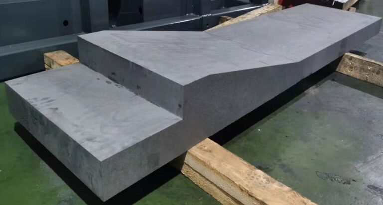
Machining converts everything between the raw envelope and the finished contour into chips. For a part machined from a rectangular blank, material utilization of 40–60% is common — the loss is proportional to the difference between blank and part volume, which is often several times the part itself. This loss is accepted as "normal" precisely because it has always been there.
Process Characteristics of Low-Kerf Graphite Cutting
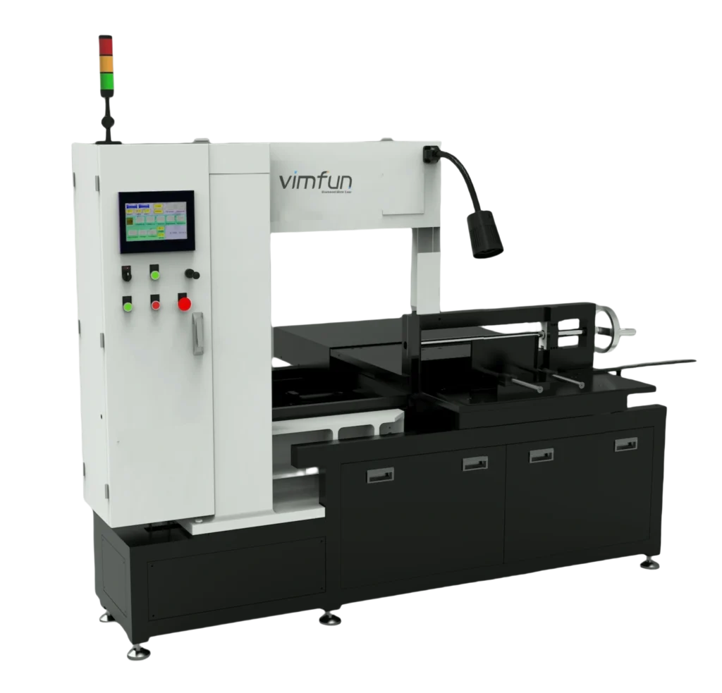
Regardless of the specific technology used, low-kerf graphite cutting processes share four defining characteristics. These are the properties to evaluate when assessing any cutting route for material efficiency — they matter more than any individual specification.
Narrow and Stable Cutting Path
The cutting path holds a consistent width from entry to exit, across the full depth of the material. Path stability matters as much as nominal narrowness — a narrow but wandering cut loses its advantage immediately.
Continuous Separation Without Overcut
The process separates material in a single continuous action — no pre-cuts, relief cuts, or corrective passes that each add their own kerf. One separation, one kerf, done.
Low Force and Controlled Contact Zone
Low cutting force means minimal deflection and vibration — the two dynamic contributors to kerf widening. A controlled contact zone keeps the engagement envelope tight and repeatable across the batch.
Kerf Consistency Across Long Cuts
The defining test: does kerf at 500 mm depth match kerf at 5 mm? Processes that hold kerf across large graphite blocks enable accurate nesting plans and predictable yield — the foundation of cost control at scale.
Manufacturing Scenarios Where Low Kerf Is Critical
Not every graphite operation needs to optimize kerf. In these four scenarios, however, kerf moves from background variable to primary cost driver — and process selection should be made with kerf explicitly on the table.
High-Value Graphite Materials
EDM-grade isostatic graphite, semiconductor-grade purified material, and specialty carbon composites where per-kilogram cost makes every millimeter of kerf a measurable expense. At these price points, kerf reduction pays back faster than almost any other process improvement. This applies directly to EDM graphite electrode cutting, where blank value is highest.
Thin Plates and Slices
Below 5 mm section thickness, the kerf-to-part ratio escalates rapidly. Battery sheets, thin electrodes, and precision substrates all fall into this range. The same slicing logic covered in 정밀 흑연 슬라이싱 applies here — with kerf as the dominant economic term.
Multi-Part Nesting from One Block
When many parts are nested from a single block, kerf determines how tightly the layout can pack. Narrower, more predictable kerf means tighter nesting, more parts per block, and less remnant material — a compound advantage that grows with nesting complexity.
Batch Production with Tight Yield Targets
Contract manufacturing with committed yield percentages leaves no room for unmeasured loss. Here kerf stability matters as much as kerf width — a process that drifts mid-batch breaks the yield plan even if its average kerf looks acceptable on paper.
How Kerf Loss Affects Yield and Downstream Processes
Kerf's cost impact does not stop at material loss. It propagates into yield, tolerance, and rework in ways that only become visible downstream — which is exactly why it is chronically underestimated.
Per-Part and Batch Yield
Kerf directly sets how many parts one block can produce. The 42-slice difference between a 2.0 mm and 0.8 mm kerf on a single cubic meter is not an edge case — it is the routine, repeatable arithmetic of every block that passes through the operation.
Chain Effect on Dimensional Tolerance
In multi-cut sequences, kerf uncertainty accumulates. If each cut's position depends on the previous cut, kerf variance compounds into positional error across the block — the last parts of a long sequence carry the summed uncertainty of every kerf before them.
커프 변동으로 인한 재작업 및 스크랩
커프 드리프트로 인해 과대 절단된 부품은 추가 수정이 필요하며, 이는 시간과 추가 재료 여유를 소모합니다. 과소 절단된 부품은 즉시 스크랩됩니다. 두 가지 실패 모드 모두 품질 시스템에서 거의 기록하지 않는 변수에 기인합니다.
커프는 제조 현장을 정의합니다
재료 활용도는 커프가 허용하는 것 이상이 될 수 없습니다. 연삭, 마무리 및 검사는 모두 최적화될 수 있지만, 절단 시 이미 손실된 재료를 복구할 수는 없습니다. 커프는 전체 비용 구조의 하한선을 설정하므로 운영자 설정이 아닌 전략적 결정입니다.
흑연 절단 시 커프에 대한 자주 묻는 질문
흑연 절단 시 커프란 무엇인가요?
커프는 절단 중에 제거되는 재료의 폭을 말합니다. 흑연 절단에서 커프는 재료 손실을 직접적으로 나타내며 수율과 비용에 상당한 영향을 미칩니다. 제거된 재료는 먼지가 되어 회수할 수 없습니다.
흑연 제조에서 낮은 커프가 중요한 이유는 무엇인가요?
흑연 재료는 종종 고가이며, 과도한 커프는 낭비를 증가시키고 사용 가능한 수율을 감소시키며 생산 비용을 상승시킵니다. 얇은 섹션 생산에서 커프 대 부품 비율은 30-50%에 달할 수 있으며, 커프는 가장 큰 제어 가능한 손실이 됩니다.
커프 손실은 기계 가공 재료 제거와 동일한가요?
아닙니다. 기계 가공은 블랭크와 완성된 부품 사이의 전체 부피에 걸쳐 칩으로 재료를 제거하는 반면, 절단 커프는 분리 경로만을 나타냅니다. 둘 다 재료 가치를 파괴하지만, 커프 손실은 더 작고, 제한적이며, 미리 예측 가능합니다.
흑연 절단에서 커프를 완전히 제어할 수 있나요?
커프는 최소화하고 안정화할 수 있지만 제거할 수는 없습니다. 모든 공정에는 절단 메커니즘에 의해 설정된 물리적 하한선이 있습니다. 공정 설계 및 경로 선택은 개별 기계 설정보다 커프 결과에 더 큰 역할을 합니다.
커프 손실은 제조 수율에 어떤 영향을 미치나요?
높거나 불안정한 커프는 스크랩률을 증가시키고, 네스팅 효율성을 감소시키며, 배치 일관성에 부정적인 영향을 미칩니다. 커프 손실은 마무리 단계 이전에 발생하므로, 다운스트림 공정에서 이를 복구할 수 없습니다. 절단 시 손실된 수율은 영구적으로 손실됩니다.
관련 흑연 절단 고려 사항
커프는 흑연 제조 전략의 한 차원입니다. 이러한 관련 공정 권한 가이드는 인접한 결정을 다룹니다. 각 결정은 비용 체인의 특정 지점에서 커프와 연결됩니다.
흑연 가공 대안
기존 기계 가공보다 절단 기반 경로를 선호하는 여러 변수 중 하나인 전체 공정 선택 프레임워크입니다.
정밀 흑연 슬라이싱
동일한 작업의 치수 정확도 측면 — 두께 제어, 평탄도 및 슬라이싱이 재작업 없는 단계인 이유입니다.
EDM 흑연 전극 절단
커프 경제학의 가장 높은 가치 응용 — 재료 비용과 일관성 요구 사항이 함께 최고조에 달하는 전극 블랭크입니다.
제조에서의 재료 활용에 대한 추가 자료: 재료 효율성 참조.
다른 것을 최적화하기 전에 실제 커프를 측정하십시오
흑연 샘플을 보내주시면 무료 테스트 절단을 실행하고 측정된 커프, 표면 품질 및 특정 블록 및 섹션 크기에 대한 재료 수율 계산을 반환해 드립니다. 구매 약정 없음.