Graphite profile cutting yield depends on both the material layout and the number of contours that meet their requirements. A sheet drawing full of tightly nested shapes can still produce poor output if the route leaves insufficient finishing stock or loses support near separation.
Measure material recovery and quality acceptance separately. They answer different questions and require different corrective actions. Combining them into one unqualified percentage can hide where a job loses useful material.
For the parent process and equipment review, see graphite profile cutting. This article focuses on outline nesting, local allowance and rejection of profiled blanks.
Define Graphite Profile Cutting Yield at a Specific Stage
State whether the accepted output is an as-cut contour or a finished component. A blank that still needs datum preparation, holes or finishing should not be counted as a finished part merely because it has separated successfully.
Use two measures where appropriate. Material recovery compares accepted blank material with the defined input allocation. Count-based first-pass acceptance compares conforming pieces with the pieces produced or attempted under the chosen definition.
Keep the denominators explicit. A layout can improve material recovery without changing the number of accepted contours. A process adjustment can improve acceptance while leaving the same skeleton and offcuts.
Retain material and drawing identity. SGL Carbon identifies different isostatic grades. Comparisons should not silently mix grades, contour revisions or thicknesses and then attribute the difference solely to the nesting method.
Check Whether the Nest Is Physically Cuttable
Review wire entry, internal openings and fixture access before maximizing the number of shapes. Every planned contour needs a feasible path and a support arrangement that remains effective through separation.
Do not assume adjacent outlines can share a cut. Shared paths can change allowance, cut order and support, and must be assessed for the actual geometry. A theoretical reduction in cut length is not proof of an acceptable production route.
Mark where the retained parts and surrounding skeleton become free. A layout that removes its supporting material too early may need another sequence, a different fixture or a larger allocation around each blank.
The graphite profile cutting yield calculation should therefore use the feasible layout, not the densest arrangement the nesting software can display. Keep any manually excluded regions visible in the material ledger.
Separate Nominal Outline Area from Useful Blank Area
Identify the nominal component area, the cut blank including finishing allowance, and the input stock allocated to the job. These areas should not be interchanged when reporting recovery.
If thickness is common and uniform for the calculation, an area ratio may be useful. If thickness or material allocation differs, use a suitable volume or mass basis instead. State the assumptions rather than choosing the basis that produces the highest percentage.
Account for internal openings as well. Removed material may be a reusable piece, an unusable offcut or part of the process loss. Its actual disposition should decide the category, not an assumption that all openings are recoverable stock.
For broader definitions, refer to graphite material utilization. Keep this article’s accounting tied to contour nesting and the blank acceptance stage.
A Labeled Graphite Profile Cutting Yield Example
Consider an illustrative constant-thickness plate with 100,000 mm² of allocated input area. Suppose ten cut blanks each contain 6,000 mm², including their finishing stock. The nominal blank-area recovery is `10 × 6,000 / 100,000 = 60%`.
If two blanks fail the agreed as-cut requirement and cannot be recovered, accepted blank area becomes 48,000 mm². Accepted-area recovery is 48%, while first-pass count acceptance is `8 / 10 = 80%`.
These are hypothetical accounting figures, not a measured Vimfun result. They deliberately show why a 60% geometric arrangement does not automatically deliver 60% accepted material.
| Illustrative quantity | Result | Meaning |
|---|---|---|
| Ten nominal blanks | 60,000 mm² | Planned blank area before quality loss |
| Eight accepted blanks | 48,000 mm² | Accepted material at the chosen stage |
| Count acceptance | 80% | Accepted pieces divided by ten produced |
| Accepted-area recovery | 48% | Accepted blank area divided by input allocation |
If rejected blanks can be reworked, record that route and its final result separately. Do not count a planned repair as accepted output before it succeeds.
Control Local Allowance, Not Just Overall Envelope
Mark critical corners, openings and narrow sections on the blank drawing. The material required for finishing can vary around an outline. An acceptable outside rectangle does not show that each local feature contains enough stock.
Define whether edge damage is acceptable within the reserved allowance. A chip outside the final envelope may have a different consequence from one that crosses a functional surface. Use the drawing requirement rather than a universal visual rejection rule.
Avoid solving low acceptance simply by adding allowance everywhere. That can increase material allocation, machining time and fixture difficulty. Identify the feature and mechanism that needs the extra stock, then qualify the revised route.
This is the distinction between graphite profile cutting yield and a generic low-kerf claim. The relevant outcome is useful contour material after the agreed checks.
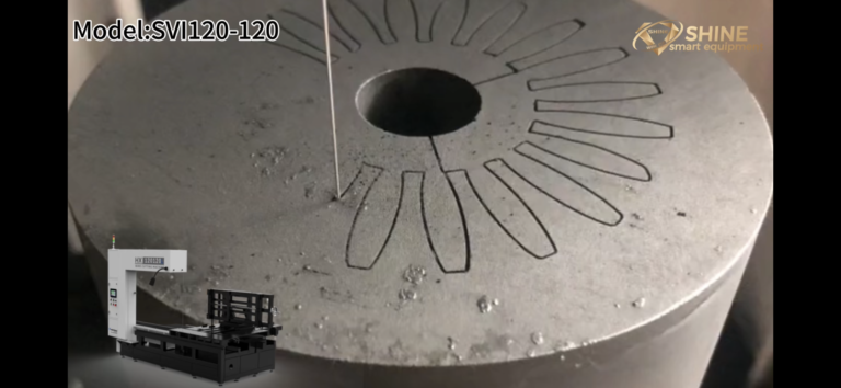
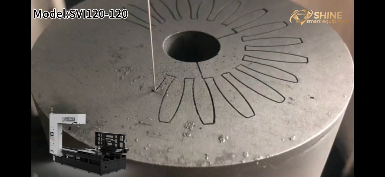
Video: Repeated rounded rectangular openings
Watch on YouTube · Vimfun Endless Diamond Wire Saw
The repeated openings provide a visual reference for layout and retained sections. The video does not establish accepted part count, kerf width or production yield.
Field Notes: Why a Different Test Cannot Supply a Profile Yield Figure
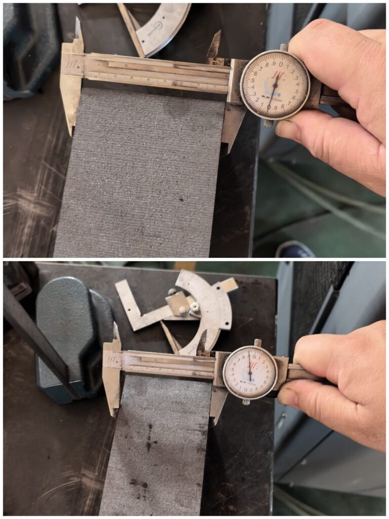
Our straight-bar cutting record reports one nominal 500 × 87 × 70 mm grade 2554 sample. Width increased from 87.00 to 87.30 mm, and thickness ranged from 69.90 to 70.10 mm with compensation off.
The recorded width taper is a genuine example of geometry that can consume finishing allowance. However, the test does not report nested contours, profile rejection counts or a complete input-material balance.
It therefore cannot establish graphite profile cutting yield. Use it as a warning to inspect local stock, not as a substitute for contour-specific production data or a claimed recovery percentage.
A useful profile field record would retain the actual nest, material allocation, drawing revision, accepted-piece count, defect map and any rework. Those are the records needed to replace the illustrative arithmetic above.
Collect Rejection Reasons That Lead to Action
Separate outline deviation, feature-location error, edge damage, insufficient allowance and handling damage. A single scrap total does not tell the team whether to change the path, fixture, measurement or layout.
Keep inspection consistent. NIST’s measurement-process chapter addresses repeatability and stability. Changing the evaluation method between trials can change acceptance counts without demonstrating a better cutting process.
Record whether a rejected blank was identified before or after handling and transfer. Preserve photographs and orientation marks where practical. The timing helps separate an observed defect from assumptions about its origin.
Use the low-kerf graphite cutting guide when kerf allocation is material to the layout. Continue to track local quality and handling separately; they are not resolved by a smaller assumed cut width.
Compare Layout Changes at the Same Delivery Boundary
When evaluating a denser layout, keep the finished requirement, material and inspection rules consistent. Record any added support, removal operation or fixture change. A smaller skeleton can come with extra work.
Check the complete part family rather than only the easiest outline. A layout may work for a broad contour and fail for a narrow version with the same overall envelope. Preserve those differences in the trial report.
Review the remaining stock with the next machining operation. If the new nest reduces recovery later, the apparent graphite profile cutting yield improvement may only have transferred the loss downstream.
Known Limitations / Trade-offs
Nesting density, support, access and finishing stock interact. The most compact arrangement is not necessarily the most reliable route, and the largest allowance is not necessarily the most economical one.
The example provides an accounting method, not a production forecast. Real recovery requires measured input allocation, actual contour area or mass, accepted output and the disposition of remnants.
No demonstrated rejection rate, minimum spacing or universal recovery percentage is established here. Those require representative contour data. Avoid using a straight-block trial or a supplier’s general precision statement to fill those gaps.
Keep Layout Revision and Acceptance Counts Together
Give every evaluated nest a revision and retain the drawing it used. Record whether a change affected part count, allowance, cut sequence or the support arrangement. Compare accepted output only after those differences are visible.
For reworked blanks, keep the original rejection reason and final disposition. A recovered piece can be useful output, but its extra work should remain identifiable. This makes graphite profile cutting yield a transparent account of the route rather than a changing definition of success.
Questions for a Production Review
Should quality acceptance and material recovery be one number?
Report them separately, then explain their relationship. This makes it possible to distinguish a layout issue from a defect problem and to assess improvements without changing the denominator.
Can all internal cutouts be counted as reusable material?
Only when their dimensions, condition and traceability meet a defined reuse requirement. Otherwise classify them honestly as unassigned remnants or scrap.
What should I send for a yield study?
The actual contour drawing, thickness, grade, nest, allowances and acceptance rules. Include counts and defect reasons from the current route. Those inputs make a graphite profile cutting yield study specific enough to support a production decision.
Use our contour-review contact page to share the layout and the features that drive rejection or finishing loss.