Outer profiles
Review the through-thickness outline, cut entry and exit, smallest local features and how the part will remain supported when separated.

Vimfun · Diamond wire cutting
Review the route from a graphite blank to a cut contour. Match the drawing, wire access and support to the equipment before deciding what can be cut and what needs finishing.
Start with the drawing
A wire-cut outline is one manufacturing step. Holes, pockets, grooves, final surface finish and tight feature relationships may require other operations.
Review the through-thickness outline, cut entry and exit, smallest local features and how the part will remain supported when separated.
Closed contours require a suitable entry and wire-threading arrangement. Confirm the machine configuration, access and whether the opening can be produced from the supplied blank.
Identify features that cannot be reached by the chosen cutting route. Reserve the stock and datums needed for subsequent milling, drilling or grinding.
Cutting capability must be checked against the specific drawing. A contour illustration does not establish arbitrary 3D capability, a blind-pocket process or a minimum achievable corner radius.
Design for the actual cutting route
Compare the complete drawing with the machine configuration. General terms such as “CNC profile cutting” do not identify the supported axes, threading method or range of producible geometry.
A drawing-led workflow
Use a representative sample to check the features that make the production part difficult.
Measure the drawing, not just the outside size
Agree the drawing revision, datum system and measurement method before evaluating the sample. Different checks answer different questions.
| Inspection item | What to review | Acceptance basis |
|---|---|---|
| Outline deviation | Compare straight sections, curves and transitions with the intended contour. | Specified profile requirement and agreed measurement coverage. |
| Feature location | Check internal or external features relative to the defined datums. | Drawing location requirements, not an isolated overall-size reading. |
| Corners & narrow sections | Inspect local geometry, entry/exit and thin features. | Allowable corner form and minimum usable stock agreed for the part. |
| Through-thickness relationship | Check whether geometry changes between accessible faces. | Required face relationship and a suitable measurement method. |
| Edge & finishing condition | Record chips, cut-surface condition and stock left for finishing. | Application-specific edge limits and downstream machining allowance. |
A single quoted precision figure cannot cover every outline, material and measurement method. Use high-accuracy graphite cutting to define the tolerance discussion.
Choose the manufacturing sequence
Compare the shape and condition required after each operation. A cut contour and a fully machined component are different outputs.
| Requirement | Profile-cutting review | Finishing or alternative route |
|---|---|---|
| Through-contour blank | Review wire access, support, contour allowance and separation. | Add finishing where the cut surface cannot meet the final requirement. |
| Internal opening | Confirm entry and threading compatibility with the machine and blank. | Use a different route if the feature is inaccessible to the cutting system. |
| Blind pocket, hole or groove | Do not infer capability from an outer-profile example. | Review milling, drilling or another suitable operation. |
| Critical datum or final surface | Measure the sample and check the stock reserved for finishing. | Add grinding or machining when required by the drawing. |
| Repeated production | Qualify locating, wire condition, inspection and accepted output. | Compare the whole route, including fixture changes and secondary work. |
For a broader comparison of stock preparation and material removal, read graphite machining alternatives.
Match equipment to geometry
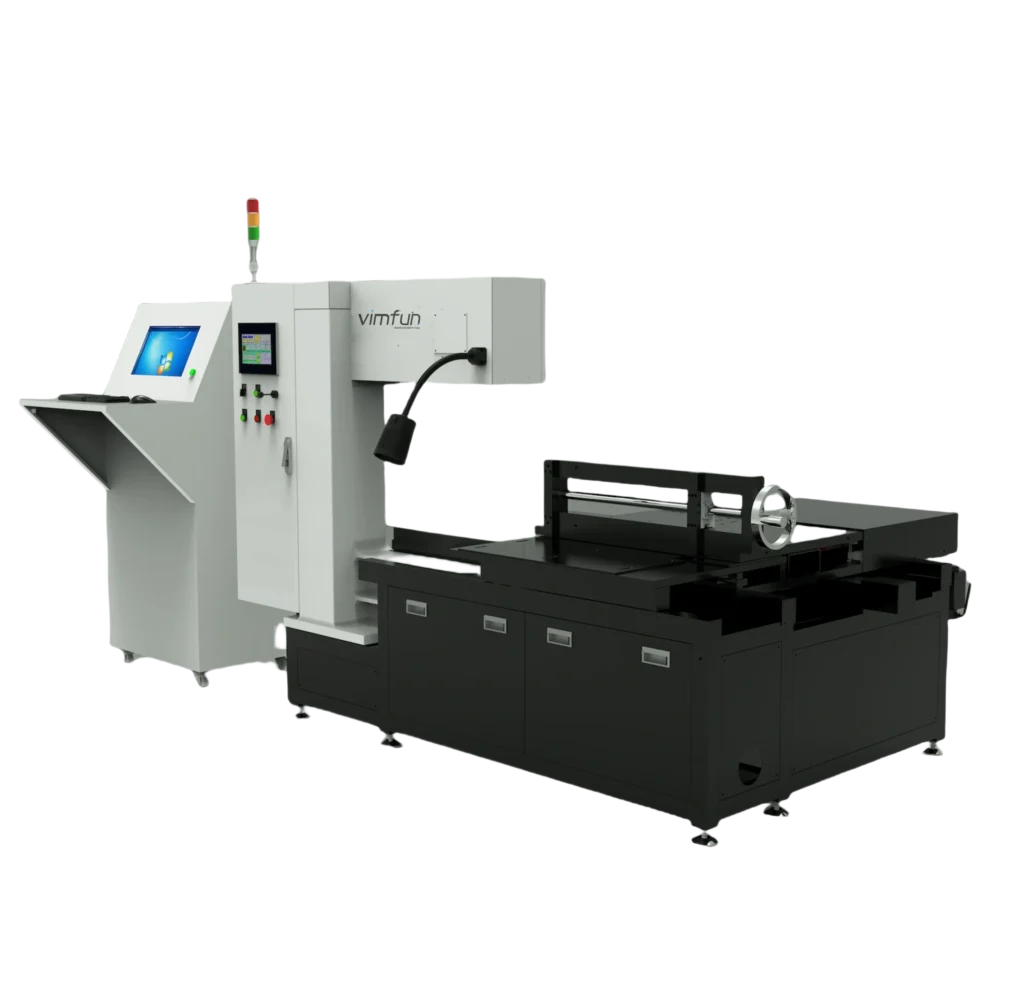
Select the machine after checking the drawing, fixture envelope, workpiece mass and access requirements. The model name alone does not establish that a feature can be produced.
Review the reachable outline, working envelope, fixture arrangement and path handling for the supplied blank.
Confirm the opening geometry, wire entry and threading arrangement before specifying closed internal profiles.
Agree material, critical features, measurements and remaining allowance. Evaluate repeatability when multiple pieces are needed.
Make the trial answer a specific question
Use the same graphite grade and representative thickness. Include the smallest local radius, narrow section, critical opening and cut entry where these features determine feasibility. A simplified outline can miss the limitations of the actual part.
Retain the drawing revision, fixture arrangement, path, wire condition and settings. Record measurements and visible edge defects alongside finishing stock. Repeat the trial where multiple pieces or extended production are part of the requirement.
Request a drawing-based trial when the available examples do not cover your geometry. Agree what the sample is intended to prove before selecting the equipment.
Continue your process review
Compare cutting with machining in the full manufacturing route.
Read the Guide →Define feature limits, measuring conditions and final-part requirements.
Read the Guide →Review thickness and face geometry when the profile starts from a sliced plate.
Read the Guide →Practical questions
Capability depends on the geometry, wire access, machine configuration and support. Check internal entry, narrow features and any non-through features from the actual drawing. Do not infer universal 3D capability from a contour-cutting example.
Confirm the proposed entry and threading arrangement, opening size, cut sequence and retained-part support. These requirements must match the specific machine configuration and workpiece.
It must be evaluated for the wire, machine, path and material conditions of the application. Supply the required radius and tolerance on the drawing so it can be assessed through a representative trial.
It may produce a suitable through-contour blank, but other operations can still be needed for holes, pockets, grooves, final datums or finish. Compare the complete manufacturing route.
Send the drawing revision, graphite grade, stock thickness and dimensions, workpiece mass, critical corners or openings, tolerances, finish requirements and quantity. Mark the surfaces that will be finished after cutting.
Start with your actual workpiece
Identify the contours and critical features. We can review access, support, equipment fit and a representative sample inspection plan.
Send Your RequirementsInclude a drawing or sample photograph where available.