Graphite profile accuracy means how the measured contour relates to the drawing under a defined inspection method. A correct overall width does not establish the position of an opening, the form of a corner or the contour through the workpiece thickness.
Before asking for an accuracy number, identify the characteristic you need to accept. Otherwise the supplier may quote a size result while the application depends on a local profile or datum relationship.
使用 graphite profile cutting topic page for the complete route. This article concentrates on inspection and acceptance of a cut outline, with final machining treated separately.

Define Graphite Profile Accuracy from the Drawing
Start with the drawing revision, material grade, stock thickness and datum system. Identify the contour segments and feature relationships that matter functionally. Label any surfaces that will be machined after cutting.
Distinguish overall size, local profile deviation and feature location. A free outline could appear close to nominal after best-fit alignment while an opening remains incorrectly positioned relative to its required datum.
Do not invent a tolerance framework when the drawing is ambiguous. Ask for the applicable specification or agree a documented sample-acceptance method. An informal “looks close” decision is not a substitute for a defined requirement.
Material identity also belongs in the record. SGL Carbon lists distinct isostatic graphite grades. Preserve the grade rather than assuming that every fine-grain material represents the same qualification condition.
Keep Size, Profile and Position Separate
Size checks answer whether a distance meets its requirement. Profile checks address the form and location of an outline under the specified evaluation. Position checks relate one feature to the drawing references.
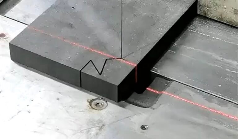
Mark the critical regions rather than measuring only convenient straight sections. Internal openings, changes in direction, entry and exit can require additional coverage. A sample report should show where measurements were taken and what was excluded.
Compare relevant sections through the thickness where the specification requires it. A satisfactory outline on one accessible face does not prove identical geometry on the opposite face or throughout the cut.
For graphite profile accuracy, one generic plus-or-minus value is therefore incomplete. Ask which feature, material, thickness, datum alignment and measuring procedure produced the number.
Select an Inspection Arrangement That Fits the Feature
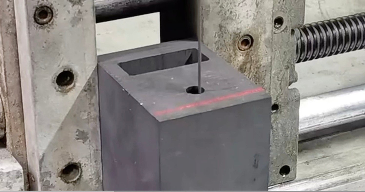
Choose equipment from the required characteristic and accessibility. Optical comparison, coordinate measurement, gauges and contact instruments have different capabilities and limitations. Do not select an instrument solely because it displays the required number of decimals.
Document how the component is supported and located during inspection. A thin or narrow region may respond differently to restraint than a substantial blank. Preserve that condition when comparing samples or evaluating a process change.
NIST discusses uncertainty budgets as a way to account for measurement contributions. For this application, record the measurement conditions that could affect the reported contour before interpreting a small difference as improved cutting.
If the inspection system cannot reach a critical region, agree an alternative before the trial. An unmeasured region should not disappear from the acceptance report simply because it was awkward to inspect.
Qualify Graphite Profile Accuracy with a Feature Map
| Region or characteristic | Inspection question | Evidence to keep |
|---|---|---|
| Long straight section | Does the measured line follow the required geometry? | Alignment, locations and deviations |
| Curve | Is the local outline consistent with the drawing? | Covered arc or sampled region |
| Corner | Is the achieved transition acceptable? | Local form and adjacent geometry |
| 内部開口部 | Is it correctly related to the datum? | Feature identity and evaluation reference |
| Thickness direction | Does the required relationship hold through the cut? | Measured face or section identities |
| Edge condition | Does damage affect the functional contour? | Location and agreed damage criterion |
Use the map for every candidate sample. The graphite profile accuracy comparison is stronger when the same regions and alignment are evaluated, even if different cutting settings were used.
Retain raw results alongside summary metrics. A maximum deviation is useful, but its location and sign can help distinguish a local feature problem from an overall offset. Neither observation alone proves the mechanism.
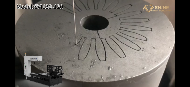
Video: Slotted graphite ring geometry
Watch on YouTube · Vimfun Endless Diamond Wire Saw
The ring presentation illustrates repeated features in a graphite component. Accuracy, slot consistency and acceptance require independent measurement; promotional claims in the video are not adopted as test results.
Field Notes: A Metrology Warning from a Different Geometry
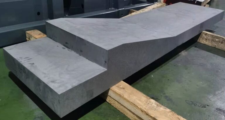
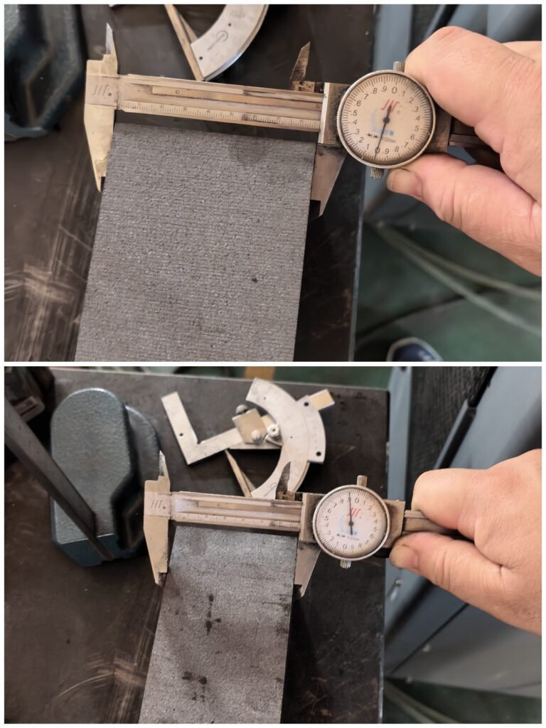
The available straight-bar trial is not a measured contour case. It produced a nominal 500 × 87 × 70 mm grade 2554 bar on an SVI250-80, with compensation off.
Width readings increased from 87.00 to 87.30 mm. Thickness ranged from 69.90 to 70.10 mm. Separate squareness-gap readings ranged from 0.09 to 0.15 mm. These measurements describe different characteristics of the same specimen.
The documented width shortcoming illustrates why one acceptable size cannot establish graphite profile accuracy. The bar record supplies no corner-form result, internal-opening measurement or through-contour profile map.
Use it to frame the inspection question, not to claim contour performance. A profile-specific field record needs the actual outline, critical-feature measurements and inspection alignment. Until then, a numerical profile capability remains unqualified.
Distinguish Cutting Error from Evaluation Differences
If two reports disagree, compare their datum definitions before changing the program. Check whether one used a best-fit alignment and the other constrained the component to its functional references.
Review the workpiece condition as well. Cleaning, handling, support and restraint can change the measurement setup. A contact on a chipped edge may also measure a different physical region from the one intended by the drawing.
Inspect the process history next: wire condition, program revision, compensation, feed and fixture arrangement. Treat these as candidate influences. A geometric pattern can guide an investigation without uniquely identifying its cause.
の 高精度グラファイト切断ガイド covers wider tolerance questions. For flat plate references, the slicing flatness and parallelism guide addresses a related but different feature set.
Decide Whether to Correct the Cut or Finish the Feature
Compare the measured deviation with the intended role of the blank. If the cut contour is final, it must meet the applicable requirement. If it is a preform, determine whether the remaining material permits the specified finishing operation.
Do not recover a single feature by moving the datum without checking the other relationships. A correction that improves an outside dimension can shift an internal feature or consume finishing stock elsewhere.
Use a representative repeat to evaluate proposed changes. Preserve drawing, material, fixture and inspection conditions where practical, and record unavoidable differences. This keeps the graphite profile accuracy discussion connected to evidence rather than a succession of program edits.
For repeat orders, add repeated locating and cutting records. One measured sample does not establish a statistical distribution or capability across wire life and material lots.
Known Limitations / Trade-offs
Dense contour sampling takes time, and some features remain difficult to reach. A simplified inspection can be reasonable for an intermediate blank if the receiving operation agrees it, but it must not be represented as full final-part verification.
A smaller reported deviation can also result from a different alignment method rather than a better cut. Preserve the evaluation definition when comparing equipment, settings or suppliers.
This article does not establish a guaranteed tolerance or universal minimum radius. Those require a profile-specific test and a measurement method appropriate to the drawing. The straight-bar readings above cannot supply those missing results.
Write a Feature-Specific Sample Acceptance Request
Start the request with the controlled drawing and the output stage. Mark which outline regions are final as-cut and which will receive finishing. Include the datum surfaces and the feature relationships that must survive that later work.
Ask for a measurement map rather than a precision headline. The map should identify covered regions, the alignment method, relevant faces through the thickness and any feature that the available equipment cannot evaluate. Keep the units and sign convention clear enough for another inspector to follow.
Request the process conditions that materially define the sample: material identity, stock thickness, fixture, wire condition, program revision and interventions. This is not a demand for every controller value; it is a way to preserve the conditions needed to interpret the result.
If the sample is accepted, state what the acceptance covers. It may establish feasibility for one contour and inspection method without demonstrating a batch distribution or another material grade. If acceptance is conditional on finishing, keep that condition beside the relevant feature.
Finally, retain a decision rule for ambiguous results. Agree who will review a disagreement and what additional measurement is appropriate. That prevents a small difference between reports from turning into an unsupported claim about the cutting system.
Questions Before Accepting a Profile Sample
Is overall width enough to judge the outline?
No, unless it is genuinely the only required characteristic. Check local form, feature location and relevant through-thickness relationships separately. Mark the functional regions before the sample is cut.
Can a best-fit report be used for every part?
Use the evaluation required by the drawing and agreed acceptance procedure. Best-fit analysis may help understand shape, but it does not automatically verify the component relative to its functional datums.
What should be requested with a precision claim?
The drawing revision, material, thickness, setup, measurement system, datum alignment, raw results and sample count. That is the information needed to interpret graphite profile accuracy without confusing a favorable reading with a qualified production capability.
Send a marked drawing through our profile-inspection enquiry page. Identify the contour, opening or datum relationship that will determine acceptance.