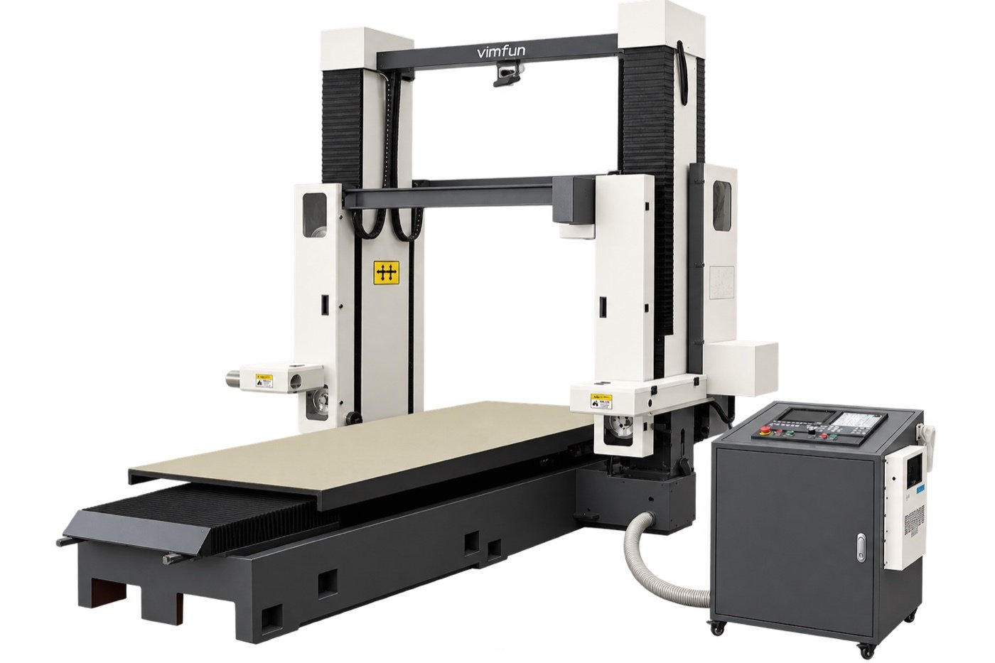
Серия SHG · Портальный станок с неподвижным столом

Большая пильная установка для графитовых блоков серии SHG

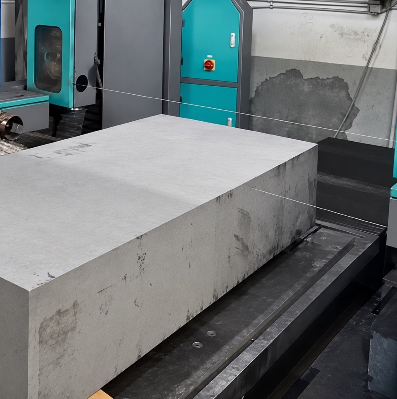
Серия SHG распиливает большие графитовые блоки на плиты, пластины и заготовки профильной формы. Отдельные горизонтальная и вертикальная режущие головки перемещаются над низким неподвижным столом, поэтому блок остается в той же установке при смене направления резки.

Выбирайте из четырех стандартных моделей в зависимости от требуемого режима резки и габаритов блока. Стандартная производительность достигает 3 300 мм в одном режиме и 2 500 мм в комбинированном режиме.

Используйте SHG в качестве установки для распиловки графитовых блоков для прямых резов. Сравните рабочие зоны для горизонтальной и вертикальной резки графита перед выбором модели.

3 300 ммдлина в однорежимном исполнении
2,500 mmдлина в комбинированном режиме
0–50 м/сскорость проволоки станка
4 моделистандартные конфигурации
Получить предложение Сравнить модели · Смотреть демонстрацию работы

Ключевые преимущества серии SHG

  • Неподвижный рабочий стол. Режущие узлы перемещаются вокруг блока, в то время как блок остается на столе.
  • Две независимые режущие головки. Выбирайте горизонтальную, вертикальную или комбинированную резку в зависимости от заготовки.
  • Низкая высота загрузки. Планируйте загрузку, опоры и установочные поверхности с учетом фактического веса и размеров графитового материала.
  • Программируемые профили X/Z. Вырезайте заготовки сложной формы на портальном станке после подтверждения контура и зазора крепления.

Смотрите работу серии SHG в действии

Демонстрация серии Vimfun охватывает три режима резки в одной установке. Используйте ее для обзора позиционирования заготовки и перемещения режущей головки вместе с таблицей производительности модели.

Watch on YouTube

Сравнение моделей SHG

Проверьте габариты вашего блока в соответствии с режимом резки, который вы планируете использовать. Размеры указаны в миллиметрах в формате длина × ширина × высота.

МодельТолько горизонтальная резкаТолько вертикальная резкаКомбинированная горизонтальная + вертикальная резка
SHG250-1202500 × 1200 × 10002500 × 1200 × 10001800 × 1200 × 1000
SHG280-1402800 × 1400 × 14002800 × 1400 × уточнить H2200 × 1400 × уточнить H
SHG300-1703000 × 1700 × 14003000 × 1700 × уточнить H2400 × 1400 × уточнить H
SHG330-1203300 × 1200 × 10003300 × 1200 × 10002500 × 1200 × 1000

Уточнить H означает, что доступная высота требует рассмотрения конфигурации. Размеры являются номинальными и подлежат подтверждению заказа.

Технические характеристики

Технические характеристикиSHG250-120SHG280-140SHG300-170SHG330-120
Ход по осям X / Y / Z (мм)2500 / 1000 / 10002800 / 1400 / 14003000 / 1400 / 14003300 / 1000 / 1000
Рабочий стол (мм)2500 × 10002800 × 10003000 × 10003300 × 1000
Вес машины, прибл. (кг)4200450046504400
Габаритные размеры, прибл. (м)3.9 × 2.3 × 2.454.2 × 2.45 × 2.54.2 × 2.8 × 2.54.5 × 2.8 × 2.5

Стандартное питание — 380 В переменного тока, трехфазное. Установленная мощность — приблизительно 9 кВт. Вес машины указан без учета упаковки. Уточните поддержку заготовки и нагрузку на стол для вашего блока.

Принцип работы портальной машины SHG с фиксированным столом

SHG удерживает графитовый блок неподвижно на низком столе. Две независимые режущие головки перемещаются по порталу, каждая со своим замкнутым режущим проводом. Цифры на схеме соответствуют списку компонентов ниже.

SHG fixed-table gantry: numbered components and X, Y, Z motion Неподвижная балка портала охватывает ширину неподвижного графитового блока на низком рабочем столе. Цифры от 1 до 5 обозначают балку портала, горизонтальный режущий узел, вертикальный режущий узел, графитовую заготовку и рабочий стол. Ось Y направлена слева направо вдоль балки поперек ширины блока, ось X — спереди назад вдоль длины блока, а ось Z — вертикально. Y · поперек ширины блокаZX · вдоль длины блока Неподвижная балка портала Вертикальный режущий узел Графитовая заготовка 134 Горизонтальный режущий узелНеподвижный рабочий стол 25 YXZ Синие пунктирные линии: замкнутые режущие провода
Функциональная схема. Положение компонентов, траектория провода и расстояния упрощены и не соблюдены в масштабе.
  1. Неподвижная балка портала. Поперечная балка охватывает ширину блока (направление Y) и несет и направляет режущие узлы над блоком.
  2. Горизонтальный режущий узел. Первый узел со своим замкнутым проводом.
  3. Вертикальный режущий узел. Второй независимый узел со своим проводом для другого направления резки.
  4. Графитовая заготовка. Блок остается на столе, пока режущие узлы перемещаются вокруг него.
  5. Неподвижный рабочий стол. Низкий неподвижный стол поддерживает блок и его приспособления. Уточните поддержку и нагрузку на стол для фактического материала.

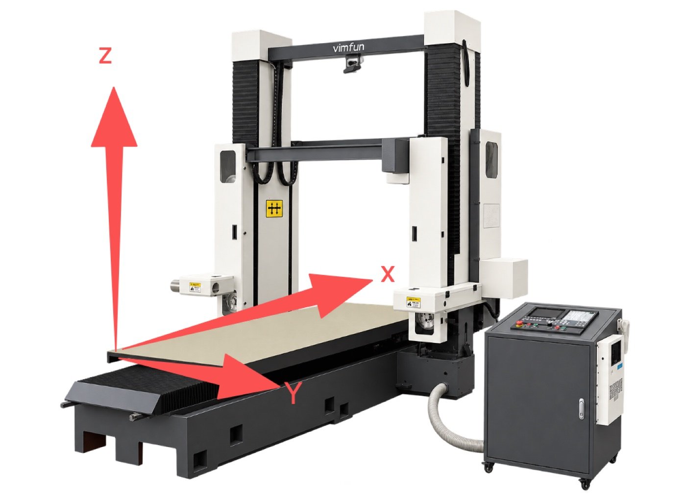
Перемещение X, Y и Z

ОсьСтрелка на схемеЧто движетсяFunction
XСпереди назад, вдоль длины блокаРежущие узлы перемещаются спереди назад вдоль длины блока; оба узла используют это продольное перемещение.Квадрирование, обрезка и длинные прямые резы.
YСлева направо, поперек ширины блока (вдоль балки)Режущие узлы перемещаются поперек ширины заготовки.Позиционирование реза поперек ширины блока.
ZВертикальныйВертикальное перемещение режущего узла.Подача сверху вниз для распиловки и разделения секций.
X + ZСинхронное движениеОбе оси перемещаются одновременно под управлением ЧПУ.Programmed contour cuts for shaped blanks.

How X and Z work together on a contour

X/Z interpolation along a programmed contour A curved programmed profile crosses a graphite block outline. At one point the cutting path is split into a horizontal X component and a vertical Z component that are moved together. Finished blank Напрасно тратить ΔXΔZ XZ Side view, X/Z planeProgrammed profile (illustrative)
Illustrative profile only. Not a real part drawing.
  1. Position. Set the cut position across the block with Y.
  2. Program the profile. The contour is defined in the X/Z plane.
  3. Interpolate. The controller moves X and Z together. At every point on the profile, the ratio of ΔX to ΔZ sets the local cutting direction.
  4. Follow the path. The resultant motion traces the programmed shape through the graphite, so one pass produces a curved or stepped edge instead of a straight cut.

Share the profile drawing so Vimfun can confirm feasibility and fixture clearance.

Wire speed and feed rate are different

Скорость движения проволоки

m/s. How fast the closed-loop wire circulates around its loop. It is set by the wire drive.

Machine range: 0–50 m/s. Initial window for isostatic and fine-grain graphite: 30–40 m/s.

Скорость подачи

mm/min. How fast CNC motion advances the cutting assembly relative to the block, which is how fast the cut progresses through the graphite.

Machine range: X 0.01–3000 mm/min; Y and Z 0.01–5000 mm/min. Initial window for isostatic and fine-grain graphite: 50–100 mm/min.

Why the two numbers are not interchangeable

Wire speed is the motion of the cutting tool itself. Feed rate is the motion of the axes. At the initial window, the wire travels roughly 18,000 to 48,000 times farther per minute than the head advances. Raising wire speed does not advance the cut, and raising feed does not make the wire run faster. Set both during commissioning for the actual grade and section size.

Why combined cutting shortens the workable length

Single-mode length matches the X travel of the model. When the horizontal and vertical units work in the same setup, both assemblies share the same X stroke instead of each having the full stroke. The block must therefore fit a shorter envelope. On the standard models, the combined-mode length is 600 to 800 mm below the single-mode length.

Single-mode and combined-mode block length by SHG model Paired bars compare the single-mode block length with the shorter combined-mode block length for each SHG model, in millimetres. 01,0002,0003,000SHG250-1202,5001,800 (−700)SHG280-1402,8002,200 (−600)SHG300-1703,0002,400 (−600)SHG330-1203,3002,500 (−800) Single mode, mm Combined horizontal + vertical, mm (reduction)
Nominal lengths from the model comparison table. Subject to order confirmation.
Example selection

A 2,400 × 1,400 × 1,200 mm block requiring both directions puts the SHG300-170 on the shortlist. Its combined-mode length and width match the nominal block size. Confirm usable height, actual stock dimensions and support clearance before selecting it. The SHG330-120 has a 1,200 mm combined-mode width, so this block exceeds its width limit.

SHG gantry overview with X, Y and Z direction arrows
X, Y and Z axis illustration

Workpiece setup

Locate the block from a stable datum, check support under the cut-off section, and allow space for dust extraction and handling before the first pass.

Cutting operations

Slab and plate cutting

Feed the cutting head down through the block to separate slabs or part off sections.

Block squaring and trimming

Cut along the block length to trim edges and prepare stock for downstream machining.

Contour cutting

Use coordinated X/Z motion to cut a programmed profile for shaped graphite blanks.

Cut Sample and Acceptance Checks

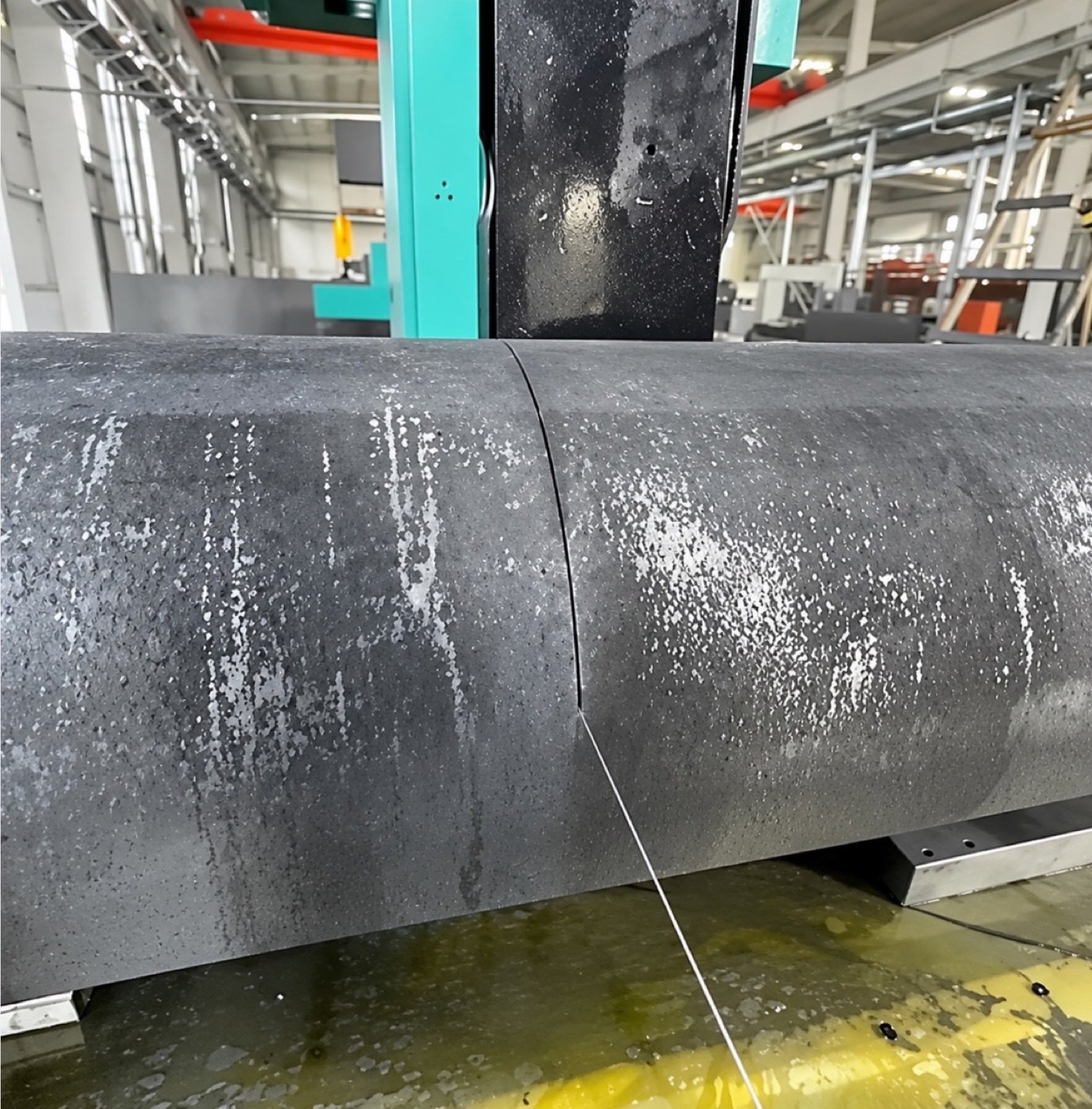
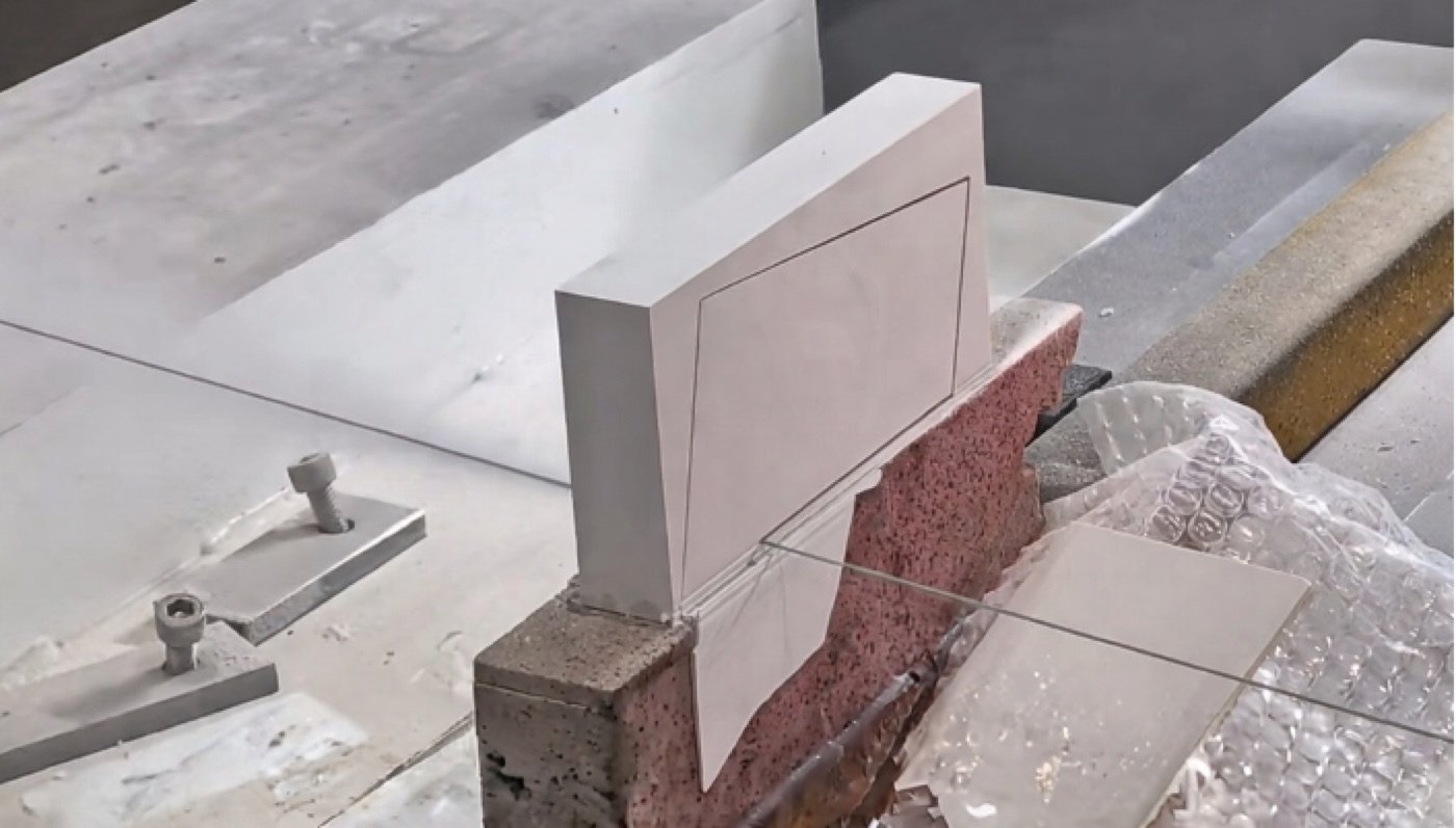
Cut sample clamped on a work surface
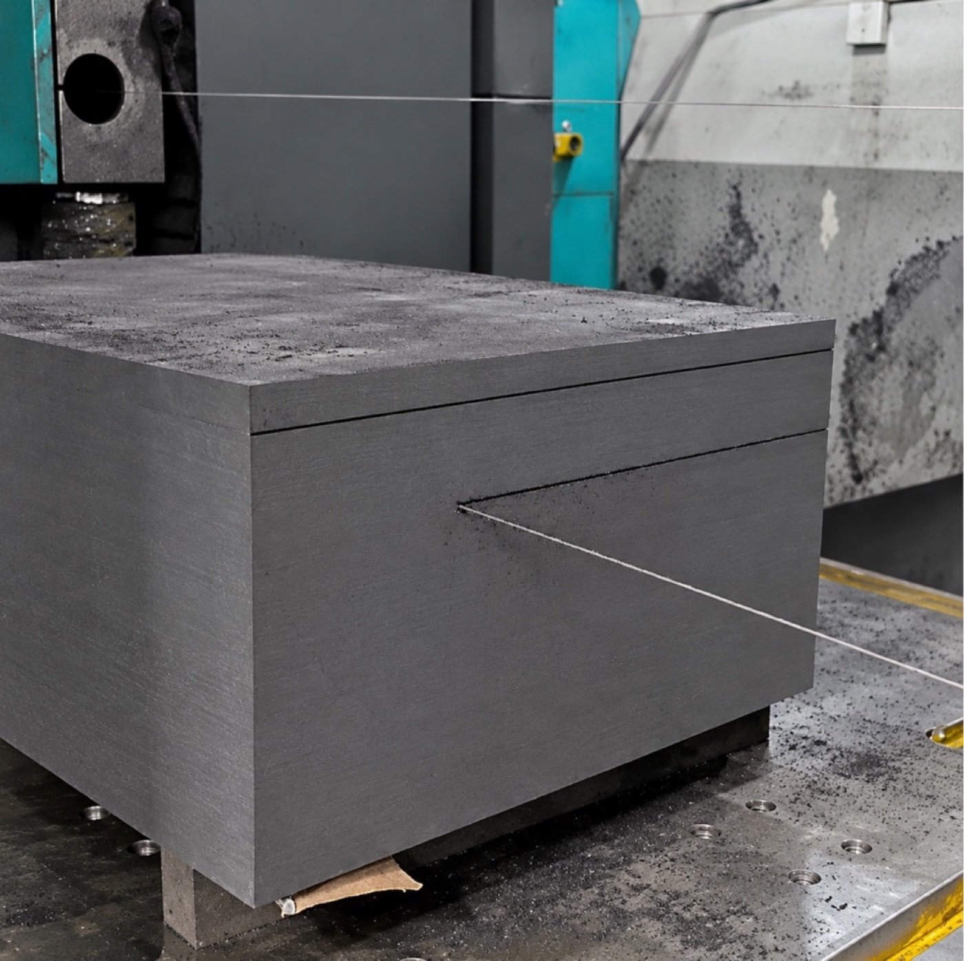
Additional sample view from the equipment document

What to verify during a trial cut

Agree on the finished blank dimensions and machining allowance before selecting feed or cutting direction. Inspect the reference face, edge condition and dimensional variation at agreed positions. Record graphite grade, cut orientation and support to make the result repeatable.

Graphite cutting setup

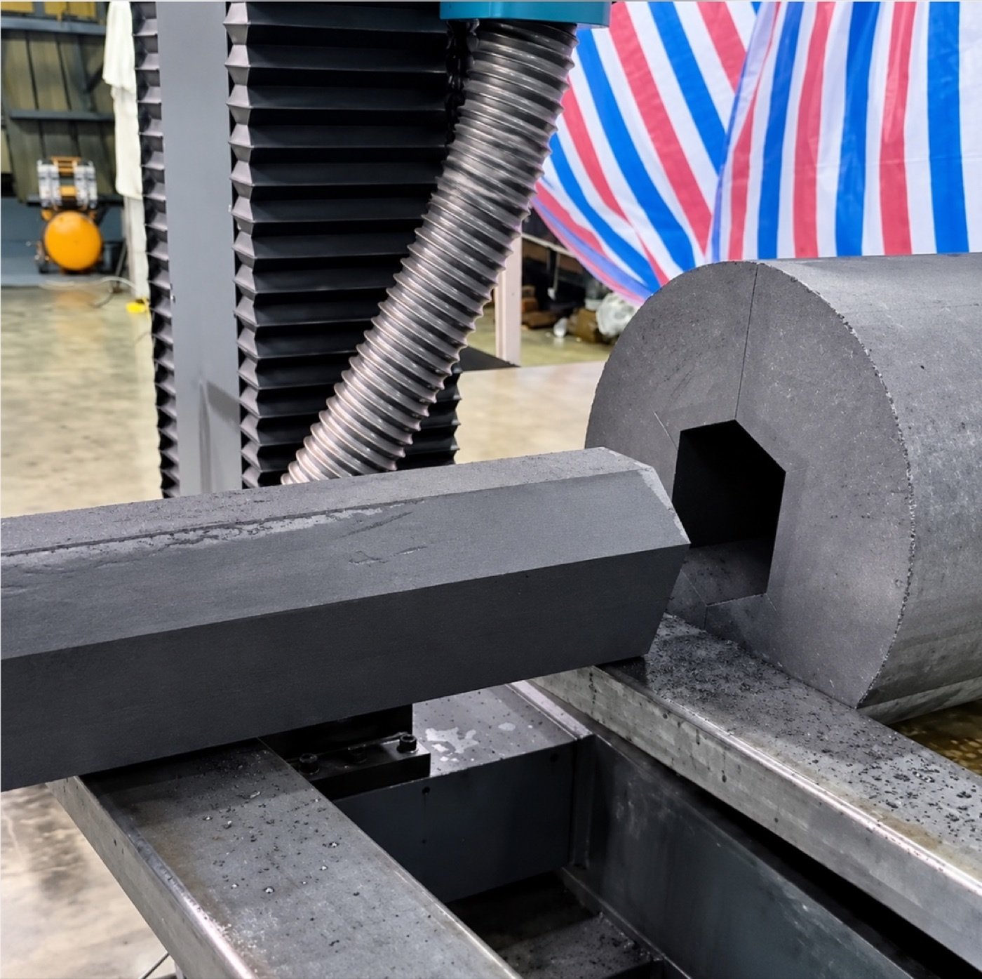
Typical materials include isostatic, extruded and fine-grain graphite. The SHG series cuts graphite dry. Plan dust extraction at the cutting zone and confirm workpiece support and fixturing for your block dimensions.

For isostatic and fine-grain graphite, the initial process window is 30–40 m/s wire speed and 50–100 mm/min feed. Initial wire diameter and tension ranges are 0.6–1.0 mm and 150–200 N. The machine wire speed range is 0–50 m/s. Set production parameters during commissioning for the actual grade and section size.

Frequently asked questions

Which model fits a 3.3 m graphite block?

The SHG330-120 accommodates a block up to 3,300 mm long in either single cutting mode, with a nominal envelope of 3,300 × 1,200 × 1,000 mm. Its combined-mode length limit is 2,500 mm.

Can the same block be cut horizontally and vertically?

Yes. The separate cutting units are mounted on one frame. Check the combined-mode envelope for the selected model before committing to the cut plan.

Can the machine cut profiled graphite blanks?

Coordinated X/Z interpolation supports programmed contour cuts. Share the profile drawing to confirm feasibility.

Does graphite cutting require coolant?

The SHG graphite process is dry. Provide dust extraction at the cutting zone.

Can Vimfun build a machine for a different block size?

X, Y and Z travel, worktable dimensions, fixturing and dust extraction interfaces can be specified to suit the installation.

Request an SHG configuration and quote

Workpiece and output

  • Graphite grade and max. block size (L × W × H)
  • Block weight and loading method
  • Cutting directions, part drawing and output per shift

Installation

  • Power supply and floor space
  • Dust collection and extraction connection

Discuss your SHG configuration

Request an SHG quote
Прокрутить вверх