SHG Series · Fixed-table gantry

SHG Series Large Graphite Block Cutting Machine

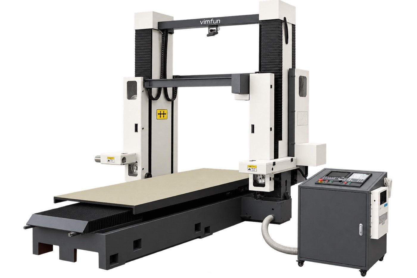
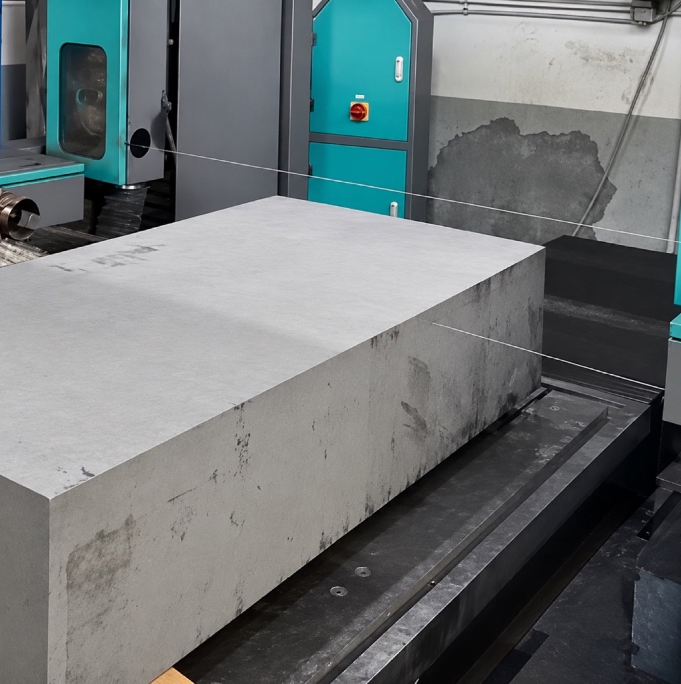
The SHG series cuts large graphite blocks into slabs, plates and profiled blanks. Separate horizontal and vertical cutting heads travel above a low, stationary table, so the block can stay in the same setup when switching cutting directions.

Choose from four standard models by the required cutting mode and full block dimensions. Standard capacity reaches 3,300 mm in a single mode and 2,500 mm in combined mode.

Use the SHG as a graphite block slabbing machine for straight cuts. Compare the working envelopes for horizontal and vertical graphite cutting before choosing a model.

3,300 mmsingle-mode length
2,500 mmcombined-mode length
0–50 m/smachine wire speed
4 modelsstandard configurations
Get a quote Compare models · See how it works

Key Advantages of the SHG Series

  • Fixed worktable. The cutting assemblies move around the block while the block stays on the table.
  • Two independent cutting heads. Select horizontal, vertical or combined cutting according to the workpiece.
  • Low loading height. Plan loading, supports and locating faces around the actual weight and dimensions of the graphite stock.
  • Programmed X/Z profiles. Cut shaped blanks on the gantry after confirming the contour and fixture clearance.

Watch the SHG series in operation

Vimfun’s series demonstration covers three cutting modes in one setup. Use it to review workpiece positioning and cutting-head movement alongside the model capacity table.

Watch on YouTube

SHG model comparison

Check your full block dimensions against the cutting mode you plan to use. Dimensions are in millimetres, listed as length × width × height.

ModelHorizontal onlyVertical onlyCombined horizontal + vertical
SHG250-1202500 × 1200 × 10002500 × 1200 × 10001800 × 1200 × 1000
SHG280-1402800 × 1400 × 14002800 × 1400 × confirm H2200 × 1400 × confirm H
SHG300-1703000 × 1700 × 14003000 × 1700 × confirm H2400 × 1400 × confirm H
SHG330-1203300 × 1200 × 10003300 × 1200 × 10002500 × 1200 × 1000

Confirm H means the available height needs configuration review. Dimensions are nominal and subject to order confirmation.

Technical specifications

SpecificationSHG250-120SHG280-140SHG300-170SHG330-120
X / Y / Z travel (mm)2500 / 1000 / 10002800 / 1400 / 14003000 / 1400 / 14003300 / 1000 / 1000
Worktable (mm)2500 × 10002800 × 10003000 × 10003300 × 1000
Machine weight, approx. (kg)4200450046504400
Overall dimensions, approx. (m)3.9 × 2.3 × 2.454.2 × 2.45 × 2.54.2 × 2.8 × 2.54.5 × 2.8 × 2.5

Standard supply is AC 380 V, three-phase. Installed power is approximately 9 kW. Machine weights exclude packing. Confirm workpiece support and table load for your block.

How the SHG Fixed-Table Gantry Works

The SHG holds the graphite block stationary on a low table. Two independent cutting assemblies move on the gantry, each with its own closed-loop cutting wire. The numbers in the schematic match the component list below.

SHG fixed-table gantry: numbered components and X, Y, Z motion A fixed gantry beam spans the width of a stationary graphite block on a low worktable. Numbers 1 to 5 mark the gantry beam, horizontal cutting unit, vertical cutting unit, graphite workpiece and worktable. Y runs left to right along the beam across the block width, X runs front to back along the block length, and Z is vertical. Y · across block widthZX · along block length Fixed gantry beam Vertical cutting unit Graphite workpiece 134 Horizontal cutting unitFixed worktable 25 YXZ Blue dashed lines: closed-loop cutting wires
Functional schematic. Component positions, wire routing and distances are simplified and not to scale.
  1. Fixed gantry beam. The cross-beam spans the block width (Y direction) and carries and guides the cutting assemblies over the block.
  2. Horizontal cutting unit. The first assembly, with its own closed-loop wire.
  3. Vertical cutting unit. A second, independent assembly with its own wire for the other cutting direction.
  4. Graphite workpiece. The block stays located on the table while the cutting assemblies move around it.
  5. Fixed worktable. A low, stationary table supports the block and its fixtures. Confirm support and table load for the actual stock.

X, Y and Z motion

AxisArrow in schematicWhat movesFunction
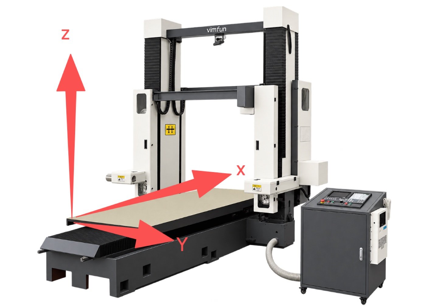
XFront to back, along the block lengthCutting assemblies travel front to back along the block length; both units share this longitudinal travel.Squaring, trimming and long straight cuts.
YLeft to right, across the block width (along the beam)Cutting assemblies move across the width of the workpiece.Positioning the cut across the width of the block.
ZVerticalVertical travel of the cutting assembly.Top-down feed for slabbing and separating sections.
X + ZCoordinated motionBoth axes move at the same time under CNC control.Programmed contour cuts for shaped blanks.

How X and Z work together on a contour

X/Z interpolation along a programmed contour A curved programmed profile crosses a graphite block outline. At one point the cutting path is split into a horizontal X component and a vertical Z component that are moved together. Finished blank Waste ΔXΔZ XZ Side view, X/Z planeProgrammed profile (illustrative)
Illustrative profile only. Not a real part drawing.
  1. Position. Set the cut position across the block with Y.
  2. Program the profile. The contour is defined in the X/Z plane.
  3. Interpolate. The controller moves X and Z together. At every point on the profile, the ratio of ΔX to ΔZ sets the local cutting direction.
  4. Follow the path. The resultant motion traces the programmed shape through the graphite, so one pass produces a curved or stepped edge instead of a straight cut.

Share the profile drawing so Vimfun can confirm feasibility and fixture clearance.

Wire speed and feed rate are different

Wire speed

m/s. How fast the closed-loop wire circulates around its loop. It is set by the wire drive.

Machine range: 0–50 m/s. Initial window for isostatic and fine-grain graphite: 30–40 m/s.

Feed rate

mm/min. How fast CNC motion advances the cutting assembly relative to the block, which is how fast the cut progresses through the graphite.

Machine range: X 0.01–3000 mm/min; Y and Z 0.01–5000 mm/min. Initial window for isostatic and fine-grain graphite: 50–100 mm/min.

Why the two numbers are not interchangeable

Wire speed is the motion of the cutting tool itself. Feed rate is the motion of the axes. At the initial window, the wire travels roughly 18,000 to 48,000 times farther per minute than the head advances. Raising wire speed does not advance the cut, and raising feed does not make the wire run faster. Set both during commissioning for the actual grade and section size.

Why combined cutting shortens the workable length

Single-mode length matches the X travel of the model. When the horizontal and vertical units work in the same setup, both assemblies share the same X stroke instead of each having the full stroke. The block must therefore fit a shorter envelope. On the standard models, the combined-mode length is 600 to 800 mm below the single-mode length.

Single-mode and combined-mode block length by SHG model Paired bars compare the single-mode block length with the shorter combined-mode block length for each SHG model, in millimetres. 01,0002,0003,000SHG250-1202,5001,800 (−700)SHG280-1402,8002,200 (−600)SHG300-1703,0002,400 (−600)SHG330-1203,3002,500 (−800) Single mode, mm Combined horizontal + vertical, mm (reduction)
Nominal lengths from the model comparison table. Subject to order confirmation.
Example selection

A 2,400 × 1,400 × 1,200 mm block requiring both directions puts the SHG300-170 on the shortlist. Its combined-mode length and width match the nominal block size. Confirm usable height, actual stock dimensions and support clearance before selecting it. The SHG330-120 has a 1,200 mm combined-mode width, so this block exceeds its width limit.

SHG gantry overview with X, Y and Z direction arrows
X, Y and Z axis illustration

Workpiece setup

Locate the block from a stable datum, check support under the cut-off section, and allow space for dust extraction and handling before the first pass.

Cutting operations

Slab and plate cutting

Feed the cutting head down through the block to separate slabs or part off sections.

Block squaring and trimming

Cut along the block length to trim edges and prepare stock for downstream machining.

Contour cutting

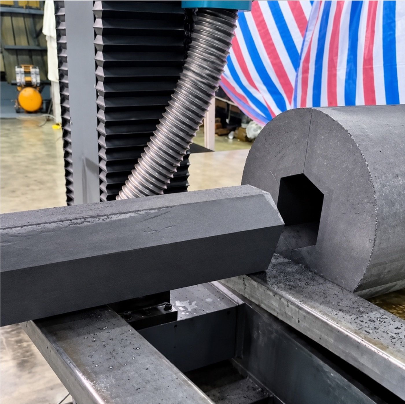
Use coordinated X/Z motion to cut a programmed profile for shaped graphite blanks.

Cut Sample and Acceptance Checks

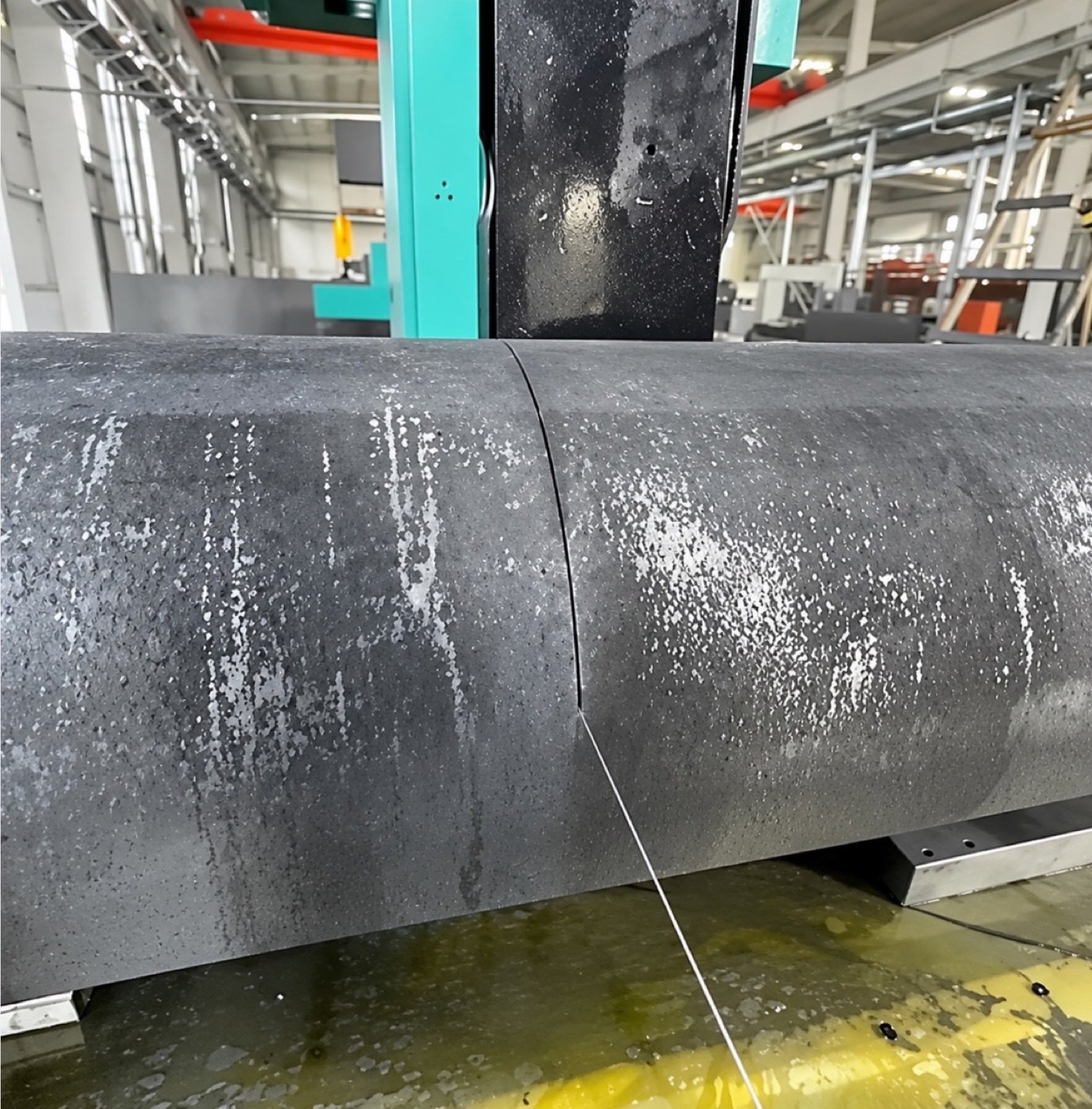
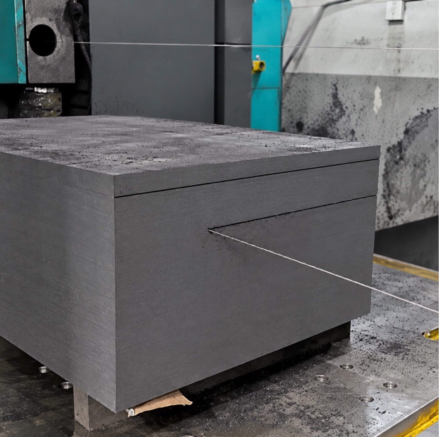
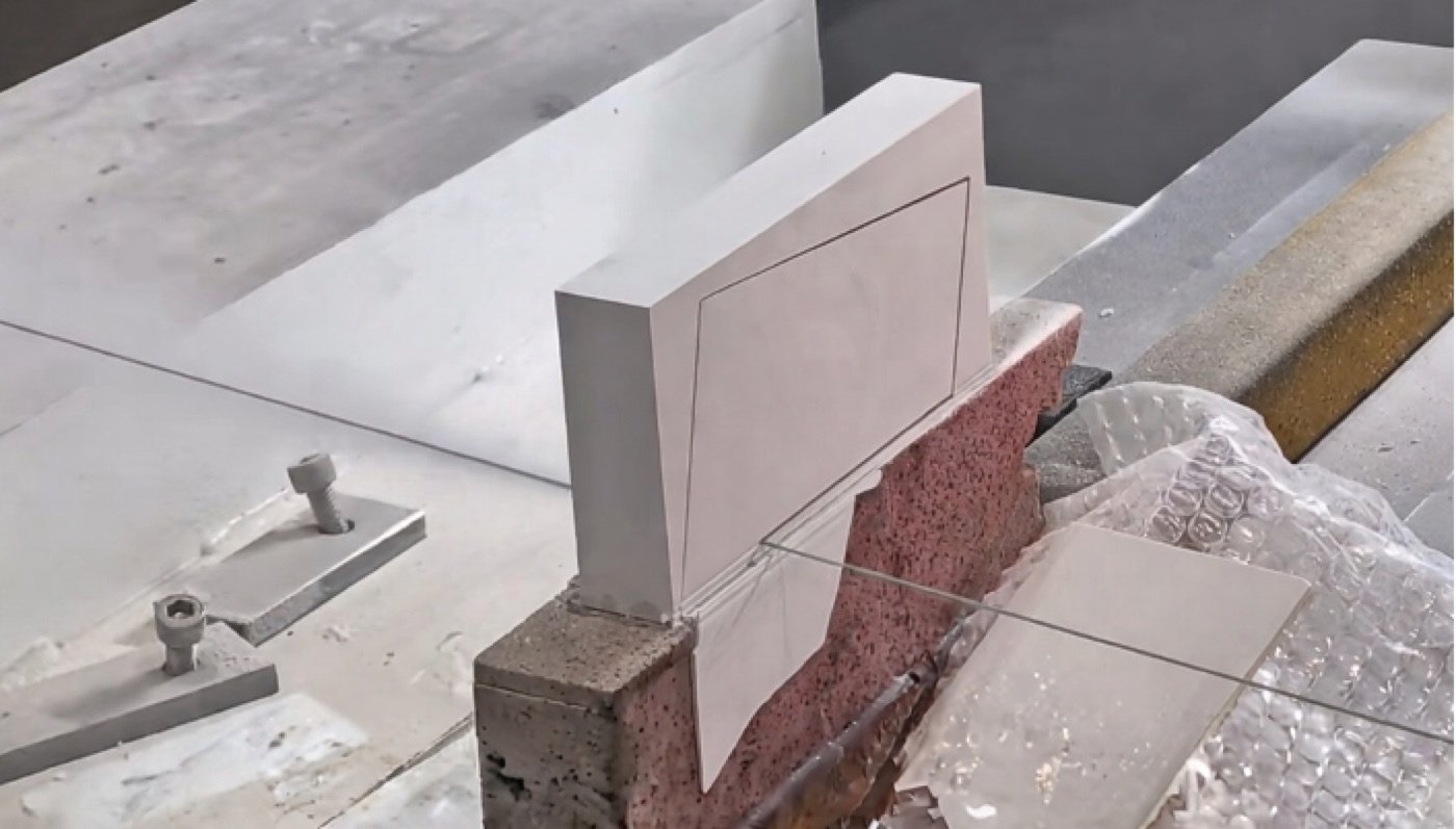
Cut sample clamped on a work surface
Additional sample view from the equipment document

What to verify during a trial cut

Agree on the finished blank dimensions and machining allowance before selecting feed or cutting direction. Inspect the reference face, edge condition and dimensional variation at agreed positions. Record graphite grade, cut orientation and support to make the result repeatable.

Graphite cutting setup

Typical materials include isostatic, extruded and fine-grain graphite. The SHG series cuts graphite dry. Plan dust extraction at the cutting zone and confirm workpiece support and fixturing for your block dimensions.

For isostatic and fine-grain graphite, the initial process window is 30–40 m/s wire speed and 50–100 mm/min feed. Initial wire diameter and tension ranges are 0.6–1.0 mm and 150–200 N. The machine wire speed range is 0–50 m/s. Set production parameters during commissioning for the actual grade and section size.

Frequently asked questions

Which model fits a 3.3 m graphite block?

The SHG330-120 accommodates a block up to 3,300 mm long in either single cutting mode, with a nominal envelope of 3,300 × 1,200 × 1,000 mm. Its combined-mode length limit is 2,500 mm.

Can the same block be cut horizontally and vertically?

Yes. The separate cutting units are mounted on one frame. Check the combined-mode envelope for the selected model before committing to the cut plan.

Can the machine cut profiled graphite blanks?

Coordinated X/Z interpolation supports programmed contour cuts. Share the profile drawing to confirm feasibility.

Does graphite cutting require coolant?

The SHG graphite process is dry. Provide dust extraction at the cutting zone.

Can Vimfun build a machine for a different block size?

X, Y and Z travel, worktable dimensions, fixturing and dust extraction interfaces can be specified to suit the installation.

Request an SHG configuration and quote

Workpiece and output

  • Graphite grade and max. block size (L × W × H)
  • Block weight and loading method
  • Cutting directions, part drawing and output per shift

Installation

  • Power supply and floor space
  • Dust collection and extraction connection

Discuss your SHG configuration

Request an SHG quote
Scroll to Top