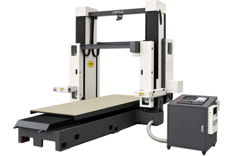
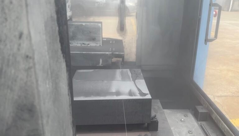
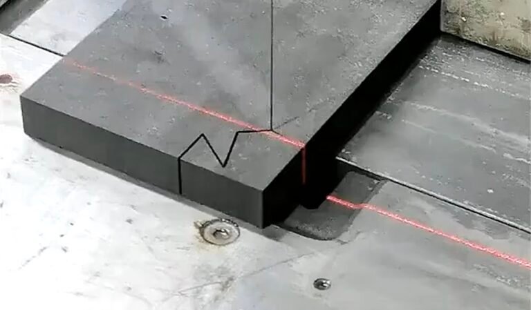
Graphite block cutting stress is a possible part of a cracking investigation, not a diagnosis that can be read from one photograph. Start by locating the defect, establishing when it was first observed and checking the material, support and cutting record.
A crack discovered after division may involve the incoming stock, handling, fixture contact, local loading or a combination of conditions. The investigation should preserve these possibilities until the evidence narrows them.
The industrial graphite block cutting topic page covers the preparation route. This article provides a structured way to collect evidence and design a follow-up trial without inventing stress values or assuming every graphite block contains the same risk.
Define the Graphite Block Cutting Stress Question
Describe the actual event first. Identify the material grade, stock dimensions, cut orientation, defect location and discovery stage. Record whether the suspect region was visible at receipt, after loading, during cutting or only after transfer.
Keep the observation separate from its proposed cause. “Crack near the clamped region” is an observation. “Clamping caused the crack” is a hypothesis requiring further evidence.
Material identity matters, but a grade label is not a complete defect history. SGL Carbon distinguishes multiple isostatic grades. Review the relevant material documentation instead of treating graphite as a single uniform specification.
Do not assign an allowable fixture pressure or universal feed range without application-specific support. The purpose of the review is to identify what needs testing, not to replace the equipment and material procedures with generic numbers.
Preserve the Defect and Its Timeline
Photograph the suspect region with orientation and scale where useful. Mark the cut direction, nearby contacts and the relationship to the final blank. Preserve the physical evidence where practical and consistent with the site’s procedure.
Review incoming inspection records. The absence of a recorded defect is not proof that the stock contained none; the original inspection may not have detected an internal or inaccessible feature. State that limitation rather than filling the gap with a confident conclusion.
Ask when the material was moved, re-clamped or separated. An observation made after transfer should not automatically be attributed to the cutting pass. Keep handling events visible in the timeline.
For graphite block cutting stress, the timeline helps determine whether a proposed mechanism is even consistent with the event. It also prevents the team from changing a process variable that had no documented relationship to the defect.
Review Support and Fixture Contacts

Map the actual seating and restraint locations before and after separation. Identify which part is retained, which part becomes free and how both are supported during the final portion of the cut.
Look for a change in support condition as material is removed. A setup photograph taken at the beginning does not necessarily represent the load path near release. Document that later condition in the trial plan.
Inspect contact surfaces and any relevant fixture records. Concentrated contact or an uneven seating condition can be considered as hypotheses, but their presence alone does not quantify stress or establish the cause of a crack.
Any proposed fixture change should be reviewed against the equipment procedure, access requirements and handling plan. Do not simply increase restraint as a universal response; the changed contact condition needs its own assessment.
Review the Cutting Record Without Confusing Parameters
Record wire identification and condition, tension, wire speed, feed, cut section, program and interruptions. Preserve units and definitions. Wire tension is not a direct measurement of stress inside the graphite workpiece.
Check whether the actual sequence matched the planned route. Pauses, repositioning or undocumented operator changes may create relevant differences between samples even when the nominal settings are identical.
Compare the difficult region with the rest of the blank. If an issue repeatedly occurs at one stage of separation, use that location to design the next observation. Do not assume that a repeated location uniquely identifies the mechanism.
The graphite block cutting stress investigation should keep measured process inputs, observed defects and inferred mechanisms in separate columns. That makes the report more useful than a list of possible causes with no evidence attached.
Use an Evidence Matrix
| Evidence category | What to collect | What it can establish |
|---|---|---|
| Incoming material | Grade, lot, supplier information and initial observations | The documented starting condition |
| Fixture and support | Contact map and conditions near release | The physical setup to be reviewed |
| Cutting history | Actual settings, sequence, wire condition and interruptions | Whether samples used comparable conditions |
| Defect location | Marked photographs and dimensions | Where and when the issue was observed |
| Inspection repeat | Consistent method and selected repeated checks | Whether the observation is reproducible |
| Follow-up comparison | Controlled change and matched evaluation | Evidence for or against a specific hypothesis |
NIST discusses variability within the measurement process. Apply that principle when deciding whether a small dimensional or observational difference between trials is meaningful.
Where a defect cannot be characterized adequately by the available inspection, seek a suitable material or metrology review rather than inventing an explanation from appearance alone.
Video: Large-block cutting context
Watch on YouTube · Vimfun Endless Diamond Wire Saw
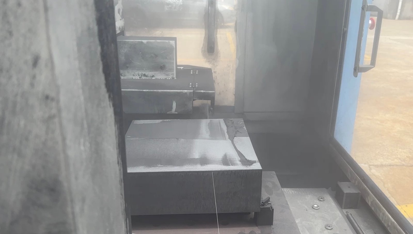
The footage provides context for reviewing the cutting setup. It is not a documented stress-cracking investigation, and visible cut lines or surface marks must not be relabeled as proven fractures.
Field Notes: A Geometric Shortcoming Is Not a Crack Test
The published SVI250-80 bar trial used grade 2554 stock, a nominal 500 × 87 × 70 mm output and 0.8 mm wire. Recorded settings included 160 N wire tension and 42 mm/min feed, with compensation off.
Width increased from 87.00 to 87.30 mm. That taper is a real shortcoming in the documented result. It is not evidence of a crack, a quantified residual stress or a validated stress-release mechanism.
The 160 N figure describes the wire setting; it cannot be reported as a workpiece stress value. Likewise, the width trend cannot be used to calculate an internal stress field from the information supplied.
For a crack-specific field record, preserve the defect, incoming material history and comparable trial conditions. The available bar case supports disciplined reporting but does not fill those evidence gaps.
Design a Follow-Up for Graphite Block Cutting Stress
Choose one plausible hypothesis supported by the timeline and location. Define what observation would strengthen or weaken it. Keep other relevant conditions comparable where practical.
For a support-related hypothesis, document the actual changed support condition rather than only renaming the fixture. For a cutting-condition hypothesis, record the specific setting and the geometry over which it changes.
Inspect the same critical region and check for unintended effects elsewhere. An apparent reduction in one defect may come with an unacceptable geometry or allowance change. Keep the blank’s complete acceptance requirement in view.
Use the graphite slicing stress discussion as related context, while recognizing that a thin plate and a large block are different configurations. Transfer questions for investigation, not unqualified parameter claims.
Keep the Production Decision Proportionate to the Evidence
If the sample contains a suspected crack affecting required material, follow the site’s nonconformance procedure before further use. The technical article should not replace the responsible engineering decision on a particular workpiece.
Document whether a proposed recovery removes the suspect region and still preserves the required geometry. Do not count a planned recovery as accepted output until the agreed inspection is complete.
For repeat production, record the frequency and conditions of actual events. A single defect can justify investigation, but it cannot establish a reliable rejection percentage or a proven comparison between cutting systems.
Known Limitations / Trade-offs
No universal graphite block cutting stress threshold, clamping force or crack-free setting is established here. Those would require material-specific data, a defined geometry and a validated analysis or test.
Changing support, allowance or sequence can affect access, material recovery and downstream work. Evaluate those trade-offs rather than assuming a more conservative route is free of production consequences.
The workflow distinguishes hypotheses from proof. A plausible explanation remains provisional when the incoming condition, load path or matched comparison is missing. Keep that uncertainty visible instead of converting it into a machine performance claim.
Retain the Reason for Each Process Change
Link the revised setup to the hypothesis it was intended to test. Record the observed result, any new issue and the conditions that were not controlled. This prevents an unconfirmed explanation from becoming a permanent production instruction.
If the evidence supports only a practical improvement, report that improvement without claiming a complete fracture mechanism. A route can be worth adopting while the detailed graphite block cutting stress explanation remains unresolved. Keep the distinction visible for later material or engineering review.
Questions for a Crack Investigation
Can the crack location identify the cause?
It can guide the investigation, but it rarely establishes the cause alone. Combine location with timing, incoming condition, support and actual process history.
Does wire tension measure workpiece stress?
No. It is a recorded machine input. Workpiece stress depends on the physical system and would need a suitable model or measurement to quantify.
What should accompany a troubleshooting request?
Material identity, blank and cut drawings, marked defect photographs, discovery stage, fixture information, settings and interruptions. Those records make a graphite block cutting stress review more useful than a request for a single “safe” feed value.
Share the evidence through our technical review contact page, including the downstream requirement and the region of material that must remain usable.