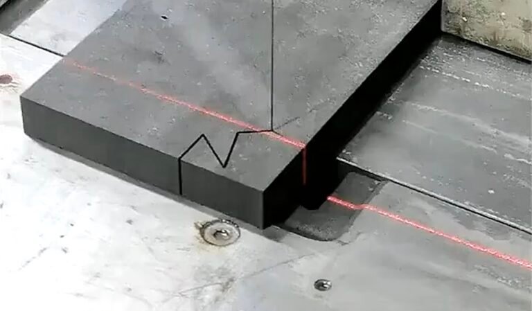
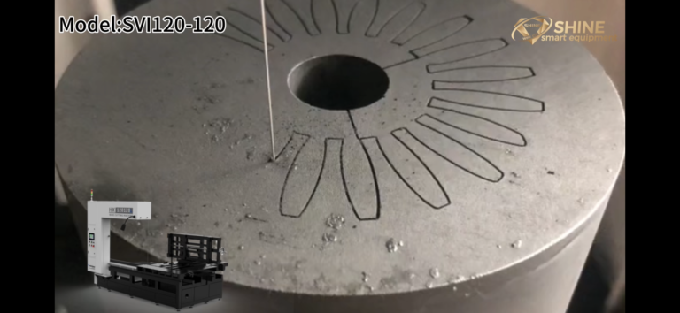
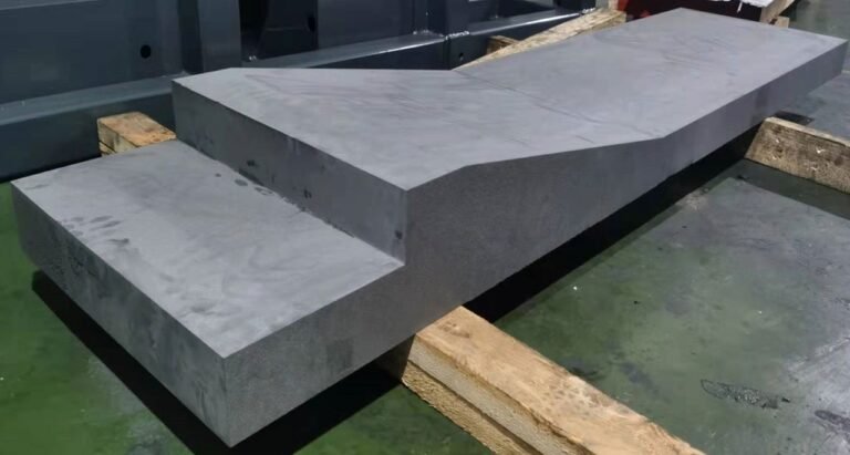
Graphite profile edge quality is a local requirement. A contour may have a clean long side while damage at its exit, internal corner or narrow feature makes the blank unsuitable for finishing.
Map the critical edges before cutting and agree what damage is acceptable at the delivery stage. An edge reserved for machining needs a different assessment from a functional edge that must remain as-cut.
The graphite profile cutting topic page covers access and equipment selection. This guide focuses on where and how to inspect contour edges, without assigning a universal chip limit to every graphite part.

Define Graphite Profile Edge Quality on the Drawing
Identify the edges that matter to assembly, handling, sealing or subsequent machining. Mark internal and external regions separately where their access or function differs.
State whether the requirement concerns visible damage, the functional envelope, a measured edge break or another specified characteristic. Avoid an unqualified instruction such as “no chips” if neither inspection method nor acceptance scale has been agreed.
Preserve material and thickness identification with the edge report. SGL Carbon distinguishes properties between isostatic graphite grades. An edge result from one grade and section should not be generalized to every supplied material.
If the edge will be finished later, show the final envelope and allowance. The presence of a visible chip and the loss of required material are related but different observations.
Divide the Contour into Inspection Zones
Mark the start, exit, straight segments, curves, corners, internal openings and narrow features. Add the regions where support changes or the retained part becomes free.
Inspect those zones consistently on each sample. A photograph of the best straight side does not represent the entire outline. Retain enough orientation information to relate every photograph to the drawing.
Check relevant edges on both accessible faces where the specification requires it. Damage may not be equally visible from one viewing direction. Define lighting and magnification when they materially affect the judgement.
For graphite profile edge quality, a location-coded record is more useful than a general “good finish” comment. It helps the process review distinguish a repeated local issue from random observations across unrelated regions.
Review Support at Entry and Final Separation
Trace how the workpiece is held as the cut progresses. Identify the restraint on the retained part and the offcut before the final connection disappears.
Treat insufficient support as a candidate influence where the geometry and observations suggest it. Do not conclude that support caused a defect merely because the defect lies near separation. Check the incoming condition, handling record and other relevant process factors.
Any fixture modification must preserve wire clearance and the required reference surfaces. More restraint is not automatically better if it introduces concentrated contact or obstructs the path.
The graphite profile edge quality review should include the actual cut sequence. A setup photograph taken before cutting may omit the physical condition that exists when the final edge is formed.
Record Graphite Profile Edge Quality in a Form That Supports Acceptance
| Record item | What to capture | Why it helps |
|---|---|---|
| Edge identity | Drawing reference and contour zone | Connects the observation to function |
| Damage position | Entry, exit, corner or another mapped region | Reveals recurring local patterns |
| Observed extent | Agreed dimensions and measurement method | Supports a consistent acceptance decision |
| Allowance relationship | Damage relative to the final envelope | Indicates whether finishing can recover it |
| Discovery stage | Before cutting, after cutting or after transfer | Prevents unsupported timing assumptions |
| Photograph | Orientation, scale where needed and useful lighting | Preserves evidence for comparison |
Do not reduce all damage to a single severity number unless the acceptance procedure defines that number. A small defect at a critical feature can matter more than a larger one in material that will be removed.
NIST’s measurement-process guidance addresses repeatability. Use consistent inspection conditions so a change in graphite profile edge quality is not merely a change in how the sample was examined.
Separate Edge Damage from Contour Deviation
A contour can deviate from the drawing without visible chipping. An edge can also contain local damage while the remaining measured outline is correctly positioned. Record both where they affect acceptance.
Do not treat surface roughness, edge condition and profile accuracy as synonyms. They require different measurement definitions and may respond differently to a process change.
Use the high-accuracy graphite cutting guide for feature tolerances. The graphite slicing defects guide provides related plate context, but contour edges need their own mapped acceptance regions.
If a report contains only an overall size and a photograph, request the missing local observations before accepting a claim about the whole profile.
Video: Graphite cut-surface appearance
Watch on YouTube · Vimfun Endless Diamond Wire Saw
This is a surface-appearance reference, not a close-up defect inspection. Chip dimensions, edge acceptance and roughness still require the checks described in the article.
Field Notes: Keep Unmeasured Edge Performance Out of the Claim
The available SVI250-80 trial documents a nominal 500 × 87 × 70 mm grade 2554 bar. It reports 0.8 mm wire, 50 m/s wire speed and 42 mm/min feed with compensation off.
Width increased from 87.00 to 87.30 mm, a recorded geometry shortcoming. The report does not provide a contour-edge damage map, a quantified chip distribution or a matched before-and-after edge study.
Those limits matter. The trial cannot supply a demonstrated graphite profile edge quality figure, and its width taper should not be relabeled as an edge-chipping failure. Different characteristics require different evidence.
For a contour-specific field note, retain real close-up photographs, the marked outline and agreed damage measurements. Until that record exists, the appropriate output is an inspection and investigation method, not an invented floor experience.
Investigate a Repeated Edge Problem
Begin with the observation and its timing. Confirm whether the damage was visible before cutting, appeared immediately after separation or was first found after handling. Preserve the sample where practical before finishing removes the evidence.
Review the material, wire condition, path, feed, support and interruption record. These are possible contributors to examine. Change one relevant condition at a time where feasible, using a comparable sample and the same inspection method.
Inspect the complete critical region after each change. An improvement at exit does not establish that a narrow internal feature is still acceptable. Keep the graphite profile edge quality comparison tied to the full acceptance map.
If the damage remains inside finishing stock, evaluate whether the current route is already suitable. Additional process tuning may offer little value if the required finished edge is reliably produced by the planned next operation.
Decide Between Process Adjustment and Finishing
Use as-cut acceptance where the edge meets the application requirement under the agreed inspection. Use a defined finishing operation where the drawing requires a condition the cut edge does not supply.
Compare the material and time consequences. Adding allowance may improve recoverability but reduce nesting efficiency. A finishing pass may stabilize the final edge while adding another locating and inspection step.
Do not repair a local feature informally without checking the resulting contour and final dimensions. Rework needs its own acceptance decision, especially near narrow sections or functional corners.
Known Limitations / Trade-offs
There is no universal acceptable chip size for every graphite contour. Grade, geometry, application and delivery condition determine the requirement. Any numerical threshold needs the drawing or an agreed customer specification.
A photograph is useful evidence of appearance but may not establish depth, subsurface condition or a full edge distribution. State what the inspection can and cannot resolve.
This guide provides no measured profile-chip reduction percentage or proven setting range. Those require representative contour tests. Do not transfer block-cutting measurements or plate-specific observations into such a claim.
Preserve a Useful Edge Sample Record
Keep the marked outline, images and inspection result together with the process revision. Label any photographs taken after handling or finishing so they are not confused with the immediate as-cut condition.
Where a defect was accepted within finishing stock, retain that reasoning. The next order may use a smaller allowance or a different final envelope, making the earlier decision inapplicable. An accepted exception should not become a universal edge limit by repetition.
Also record what improved after a controlled change and what remained unmeasured. If only the exit region was examined, do not describe the result as an improvement across the whole contour. A limited but well-defined finding is more useful for the next trial than a broad claim with missing coverage.
This sample record supports later discussion with the customer, cutting operator and finishing team while keeping the observed edge condition separate from its proposed cause.
Questions for an Edge Review
Should every visible chip cause rejection?
Use the applicable requirement. Identify whether the damage affects the final envelope, functional edge or planned finishing stock. Reject or rework according to that condition rather than appearance alone.
Can a slower feed be assumed to solve the problem?
No. Review the complete evidence and qualify any change on a representative sample. Feed is one recorded variable among material, wire, geometry, support and handling conditions.
What should I send for troubleshooting?
The drawing, grade, thickness, marked damage locations, useful close-up photographs, discovery stage and actual process conditions. Those details make a graphite profile edge quality review specific enough to guide a controlled trial.
Share the marked contour through our technical enquiry page. Include which edges are final and which will be machined later.