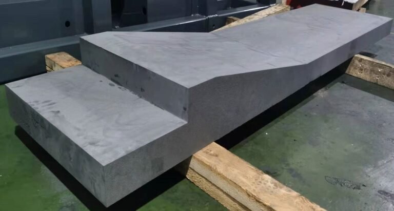
A graphite block cutting process should finish with a blank that the next operation can locate, measure and machine. Separating the stock is only one part of that job: the cut sequence, support and inspection plan determine whether enough usable material remains.
Start with the required blank drawing, not a machine feed setting. A block intended for thin slicing needs a different preparation route from a bar that will be milled into electrode blanks. Both may use diamond wire, but their locating faces and acceptance checks are different.
Le industrial graphite block cutting topic page covers equipment and application selection. Here the focus is the sequence an operator and process engineer can document, qualify and hand over.
Define the Output of the Graphite Block Cutting Process
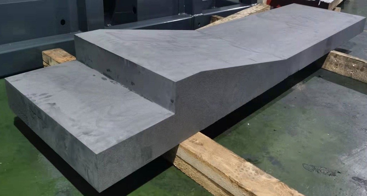
Specify three geometries separately: incoming stock, cut blank and finished component. Label which faces are final and which carry machining allowance. If the blank drawing simply repeats finished dimensions, the cutting team has no explicit allowance for removing a damaged edge or correcting a reference face.
Choose the initial locating surface and the face that the next machine will use. These are not necessarily the same. Record whether the stock will be rotated between cuts, because each repositioning changes the chain of reference surfaces.
Keep the material grade and lot identification with that plan. SGL Carbon identifies several isostatic graphite grades with distinct properties. A successful setting on one supplied grade is a starting record, not an automatic recipe for another.
For a mixed order, group blanks by compatible stock and inspection requirements rather than grouping everything under “graphite.” That makes later comparisons useful when a particular section or material lot behaves differently.
Inspect Incoming Stock Before Loading
Measure the stock envelope at enough positions to establish whether the proposed blanks fit. A nominal supplier dimension does not show local damage, an irregular seating face or the stock needed to establish a datum.
Photograph visible corners and mark any suspect region before cutting. Record the inspection method and whether the observation was made before or after unpacking. This provides a baseline when a defect is discovered later; it does not prove that every internal defect was detectable at receipt.
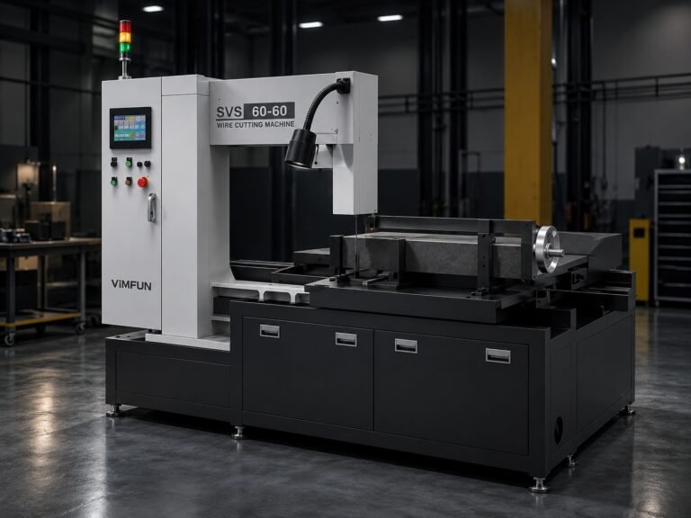
The loading review should include mass, access and support. Confirm the applicable machine and handling limits from the actual equipment documentation. Do not estimate table capacity from the apparent size of a machine photograph.
Check that the fixture and the block fit together within the usable working area. A workpiece that fits on its own may leave no clearance for a clamp, support or separated piece. Keep personnel clear of the separation zone and use the site’s approved loading procedure.
Lay Out Cuts and Preserve the Reference Faces
Prepare a cut sketch showing retained blanks, offcuts and the order of separation. Include the expected kerf allowance and the stock reserved for finishing. Mark where the block will be located after each change in orientation.
Think through the last part of every cut. The separated piece needs support before it becomes free. A route that works while the block is intact may become unsuitable when only a narrow remainder is held.
Avoid using a freshly cut face as a precision reference merely because it looks smooth. Inspect the feature relationship first. A surface can have a good appearance while remaining unsuitable as a datum for the next setup.
When blanks will later become plates, coordinate the preparation plan with the precision graphite slicing route. The useful output may be a stable stock section for slicing rather than the smallest possible blank from the first operation.
Set Up the Graphite Block Cutting Process
Document wire identification and condition, the proposed tension and speed, feed, support arrangement and relevant compensation settings. Copy values only from an approved equipment procedure or a representative qualified trial.
Check the definition of each parameter. Wire speed describes movement along the wire; feed describes advance through the workpiece. Substituting one for the other makes a process sheet unusable, even when both values have plausible units.
Keep the first trial controlled. If feed, wire, support and compensation all change together, an improved result will not reveal which change helped. Select the feature to investigate, preserve the other relevant conditions and record any unavoidable difference.
The graphite block cutting process also needs an interruption plan. Record how the workpiece will be checked after a pause or restart. Do not assume a restarted cut is equivalent to an uninterrupted sample without inspecting the affected region.
Inspect Features Instead of Reporting One Precision Number
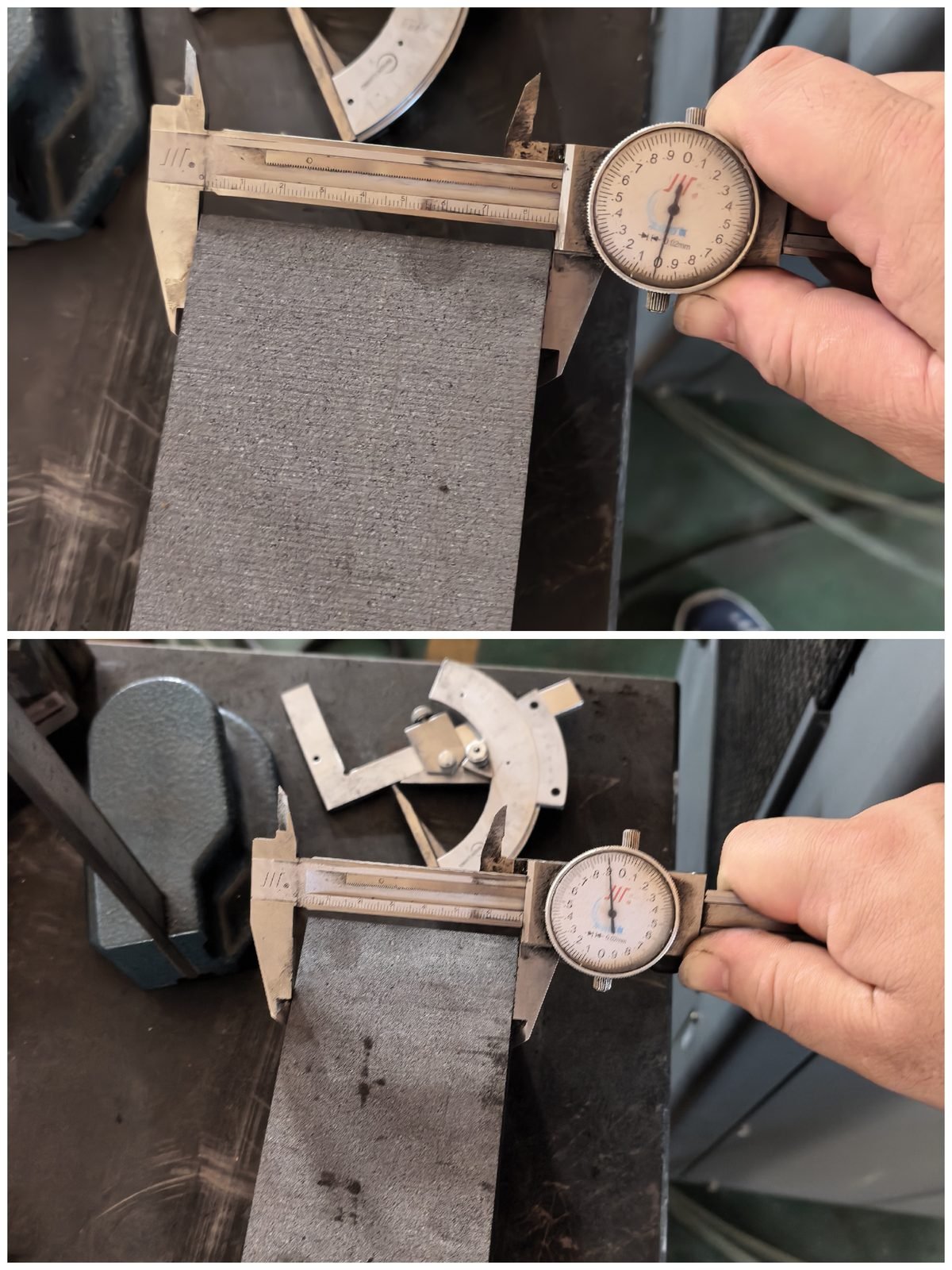
Use an acceptance sheet that distinguishes size from geometry. Width readings, squareness gaps and face-indicator readings describe different characteristics. They cannot be combined into a single generic “accuracy” result.
| Check | Enregistrer | Decision supported |
|---|---|---|
| Width and thickness | Individual readings and their positions | Whether finishing stock remains |
| Reference face | Support, sampling positions and readings | Whether the next setup can locate reliably |
| Adjacent faces | Datum and measurement method | Whether their relationship suits the next operation |
| Edges | Location, photographs and allowable damage | Whether chips consume required material |
| Cut conditions | Settings, wire history and interruptions | Whether the trial can be repeated meaningfully |
NIST’s uncertainty guidance explains why the quality of a measurement matters to its use. In practice, choose an inspection method capable of supporting the particular acceptance decision. More decimal places on a display do not settle that question.
Video: Large-block cutting setup
Watch on YouTube · Vimfun Endless Diamond Wire Saw
The gantry-machine overview and block-cutting footage provide context for stock division and handling. The video does not replace a setup sheet or blank inspection record.
Field Notes: The Width Taper That a Summary Would Hide
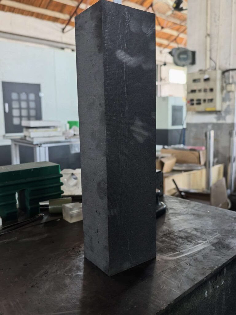
Notre documented isostatic graphite trial produced one nominal 500 × 87 × 70 mm bar from grade 2554 stock on an SVI250-80. Six cuts used 0.8 mm wire, 50 m/s wire speed, 160 N tension and 42 mm/min feed; total cutting time was 45 minutes.
Wire-diameter compensation was off. The reported width readings were 87.00, 87.10, 87.20, 87.20, 87.30 and 87.30 mm. Thickness readings ranged from 69.90 to 70.10 mm. The width trend is the important shortcoming for this process discussion: it changes how much stock the next operation must remove.
The published record attributes the taper to the uncompensated cutting condition, but it does not provide a matched repeat with compensation enabled. Treat that attribution as the trial interpretation, not as independently isolated proof of the cause.
This was one bar measured with shop-floor instruments. It was not a production capability study, a full-surface flatness certification or a surface-roughness test. The useful lesson is to retain all readings and the settings that produced them.
Release the Blank to the Next Operation
Identify each accepted blank, its orientation and the reference surface to be used next. Attach the inspection result and note any conditional acceptance, such as a face that must be machined before it can serve as a datum.
Do not silently reclassify an undersized region as an acceptable offcut after the job has been costed. Record what happened to the material. The low-kerf graphite cutting guide explains why kerf and usable material recovery need to be considered together.
If another team will perform final machining, agree how they will verify the incoming blank. A handover drawing with marked datums and actual dimensions is more useful than a note saying “cut complete.”
Preserve nonconforming samples long enough to understand the issue where practical and permitted by the site’s procedure. Photograph and identify them before any corrective machining removes the evidence.
Known Limitations / Trade-offs
A graphite block cutting process qualified on one cross-section does not establish behavior across every block size. Changes in support, cut length, material grade and wire condition require an engineering review and, where necessary, another representative trial.
Additional inspection and conservative allowance consume time or material. Too little inspection can transfer an expensive correction to the next machine. Choose the balance using the acceptance requirements and the consequences of an unusable blank, rather than chasing the shortest first cut.
Diamond wire preparation also does not remove the need for holes, pockets or finished surfaces where the component drawing requires them. Keep those operations visible in the route and the quotation.
Keep the Trial Record Usable
Assign one process-sheet revision to the accepted setup. Keep the cut sketch, material identity and inspection map together rather than storing disconnected photographs and parameter screenshots. This makes the graphite block cutting process repeatable as a documented route and helps explain which conditions a later revision changed.
Questions Before a Production Trial
What should be on the trial request?
Include material grade, incoming dimensions and mass, target blank geometry, datum requirements, finishing allowance and planned quantity. Mark the feature that the trial must prove, such as an adjacent-face relationship or the stock remaining after division.
Should the first sample be the easiest blank?
Use a representative sample. If a long cut, repeated repositioning or an awkward support condition determines feasibility, a short uncomplicated coupon will not answer the production question. Start with a manageable trial that preserves the relevant difficulty.
When is the process ready for repeat orders?
When the documented setup produces accepted blanks under the conditions that repeat orders will encounter. Keep the graphite block cutting process sheet connected to inspection records, wire history and any agreed requalification triggers. A successful photograph is evidence of a cut, not of sustained production.
Send your stock drawing and acceptance requirements through our cutting-trial contact page. Include the downstream operations so the trial evaluates a usable blank rather than an isolated cut.