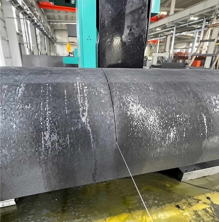
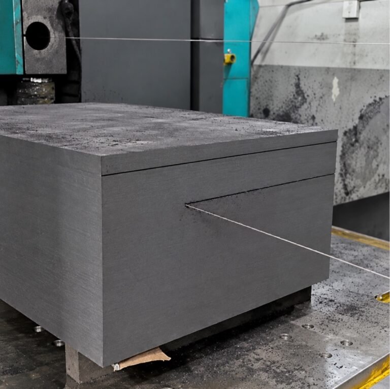
Graphite slab cutting from large blocks needs a plan for both the retained stock and the section that becomes free. A straight cutting path is only part of the job: the separated slab must remain controlled, and the blank must retain enough material for its next operation.
Define the required output before selecting the cut position. A thick plate blank for later machining is a different deliverable from a finished thin sheet. Thickness, face condition, datum requirements and handling access should be written into the trial request rather than inferred from an attractive cut surface.
Le large-block cutting topic page covers the broader initial-division route. This article stays with slab separation, support and handover; the precision graphite slicing guide addresses the separate thin-slicing discussion.
Five Pre-Trial Checks
Use these five checks as an index to the detailed review below. They organize the proposed job; they are not a claim of measured SHG performance.
- Define the required slab blank.
- Support retained and separated stock.
- Plan the removal path.
- Reserve the agreed finishing stock.
- Inspect the blank after separation.
Specify the Blank for Graphite Slab Cutting from Large Blocks
Keep the incoming stock dimensions, slab blank dimensions and finished component dimensions separate. The first operation may deliberately leave additional material for establishing reference faces or finishing the thickness later. Do not remove that material simply to make the cut blank resemble the final drawing.
Identify which face will locate in the next fixture. Then mark which opposite face carries the remaining thickness allowance. Where the route includes several slabs from one block, give every proposed blank a location on the cut sketch so the cumulative material requirement can be reviewed.
Material identification stays with the plan. SGL Carbon’s isostatic graphite information explains that grades have distinct properties. A previous cutting result on one stock family does not qualify every supplied grade or every section size automatically.
State whether the slab is accepted directly after separation or only after a subsequent finishing operation. That decision affects the measurement plan, the material reserved and what the receiving team can legitimately expect from the blank.
Design the Separation Sequence Around the Cut-Off Section
Draw the retained block and the slab that will separate, including their support locations. Review the final stage of the cut before starting. Support that is adequate while the material is continuous may not control the part once the remaining connection disappears.
The process review should identify the separated section’s mass, orientation and intended removal method. Do not assume the cutting wire will hold it after separation, and do not treat a nearby table surface as an approved support without checking the actual arrangement.
Make the removal path part of the fixture review. A slab may fit the cutting envelope yet be awkward to extract with the available equipment. Access for lifting, the state of the remaining stock and clearance around the cutting assemblies all need agreement before the trial.
Keep handling decisions under the site’s approved procedures and equipment limits. No lifting capacity, support spacing or fixture load rating can be established from the SHG photograph alone. Request the missing values for the actual block and installation.
Where the SHG Top-Down Operation Fits
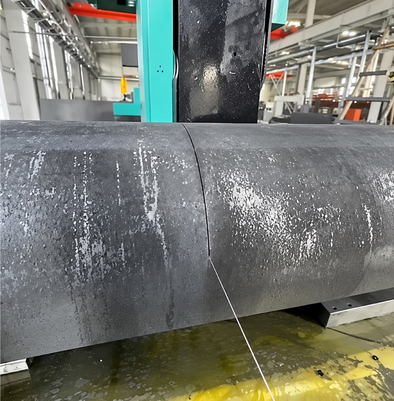
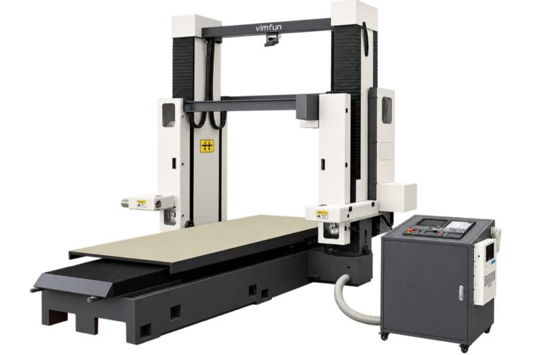
La description publique du produit associe le mouvement Z à une alimentation descendante pour le débitage et la séparation de sections. Des ensembles de coupe séparés fonctionnent au-dessus d'une table basse et stationnaire. L'orientation de coupe prévue doit être confirmée sur le dessin d'installation plutôt que déduite uniquement des mots directionnels dans le titre d'une vidéo.
Examinez le Configurations de découpe de dalles et plaques SHG après avoir défini l'opération. Le SHG330-120 liste une enveloppe nominale de 3 300 × 1 200 × 1 000 mm dans une seule direction, tandis que l'enveloppe combinée est de 2 500 × 1 200 × 1 000 mm.
Si la voie de la dalle nécessite également une coupe dans l'autre direction sans déplacer le stock, l'enveloppe combinée plus courte devient pertinente. Ne citez pas la longueur en mode unique comme taille acceptée pour une configuration bidirectionnelle.
Pour le SHG300-170, l'enveloppe horizontale uniquement est indiquée comme 3 000 × 1 700 × 1 400 mm, tandis que la colonne combinée indique 2 400 × 1 400 mm avec la hauteur à confirmer. Ce sont des dimensions nominales de configuration, pas une capacité de débitage démontrée ou une charge admissible.
Vidéo : Découpe de blocs par portique
Watch on YouTube · Vimfun Endless Diamond Wire Saw
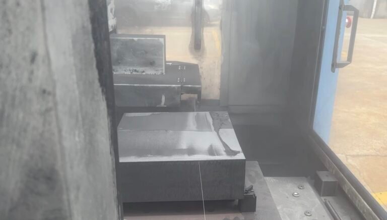
Cette référence de découpe de blocs par portique fournit un contexte de processus pour la découpe de dalles de graphite à partir de grands blocs. Le modèle exact, l'épaisseur de la dalle, le support de coupe complet et les dimensions après retrait ne sont pas vérifiés par le clip ; qualifiez ces détails par rapport au travail proposé.
Set Graphite Slab Cutting from Large Blocks Apart from Thin Slicing
La distinction réside dans le résultat requis et la voie d'acceptation, et non dans un seuil d'épaisseur universel fourni ici. Une ébauche de dalle peut contenir du stock pour une correction ultérieure des faces, tandis qu'un travail de découpe fine peut mettre l'accent différemment sur la distribution de l'épaisseur et la manipulation de chaque feuille.
Évitez d'utiliser une démonstration de feuille mince pour valider une configuration de dalle épaisse. La section du stock, le support et les conditions de retrait peuvent être différents même si les deux processus utilisent un fil diamanté. De même, une vidéo d'un grand bloc en cours de séparation n'établit pas l'épaisseur minimale acceptable de la feuille.
Lorsque la dalle deviendra une matière première pour un tranchage ultérieur, coordonnez ses surfaces de référence et ses dimensions avec cette opération suivante. La première équipe de coupe doit savoir quelle face doit rester utilisable pour le positionnement et quelle quantité de matière est nécessaire pour le parcours de tranchage.
Cette limite empêche deux substitutions trompeuses : utiliser une revendication de tranche mince comme résultat d'acceptation de dalle, ou utiliser une photographie de coupe de dalle comme preuve de production de feuille de précision. Chaque parcours nécessite des preuves correspondant à son livrable réel.
Vidéo : Un parcours de tranchage multi-fils distinct
Watch on YouTube · Vimfun Endless Diamond Wire Saw
Plusieurs fils coupent simultanément le stock de graphite dans cette référence multi-fils. Il s'agit d'un arrangement de tranchage distinct, et non d'une preuve que le SHG standard utilise plusieurs fils par ensemble de coupe. Comparez-le uniquement comme un parcours différent ; aucun avantage en termes de tolérance de dalle, de sortie acceptée ou de taux de production n'est établi ici.
Plan Material for Graphite Slab Cutting from Large Blocks
Établissez un croquis de coupe qui tienne compte des ébauches conservées, du stock de finition prévu, des pertes de séparation et des bords inutilisables. Utilisez l'allocation de trait de coupe qualifiée réelle lorsque disponible. Le diamètre du fil et l'épaisseur de la dalle ne sont pas interchangeables avec la perte de matière mesurée.
Pour les dalles répétées, examinez l'exigence cumulative plutôt que de vérifier uniquement la première ébauche. Un parcours qui laisse suffisamment de stock au début peut produire un reste final sous-dimensionné si la disposition ignore les pertes entre les sections.
N'attribuez pas un pourcentage de récupération attrayant au seul dessin. La sortie acceptée dépend de la survie des ébauches séparées lors de la manipulation et de leur conformité à la géométrie et aux exigences de bord convenues. Séparez l'efficacité nominale de la disposition de la récupération de matière acceptée.
Si les données du processus sont incomplètes, indiquez les termes non résolus sur la feuille de planification. C'est plus utile que d'insérer un trait de coupe ou une allocation devinée et de présenter le résultat comme un plan de production validé.
Keep Wire Speed and Feed Rate Distinct
The SHG product page lists a machine wire-speed range of 0–50 m/s. It separately gives initial isostatic and fine-grain graphite windows of 30–40 m/s wire speed and 50–100 mm/min feed. These are manufacturer starting recommendations, not measurements from the proposed slab job.
Wire speed describes circulation of the cutting wire; feed describes the relative advance of the cutting assembly through the material. Increasing one does not mean the other has increased. Record both with their units on the trial sheet.
For graphite slab cutting from large blocks, select commissioning conditions against the actual grade, section and support arrangement. This article supplies no universal production setting, guaranteed cutting time or optimum feed for a particular slab thickness.
Inspect Graphite Slab Cutting from Large Blocks at Handover
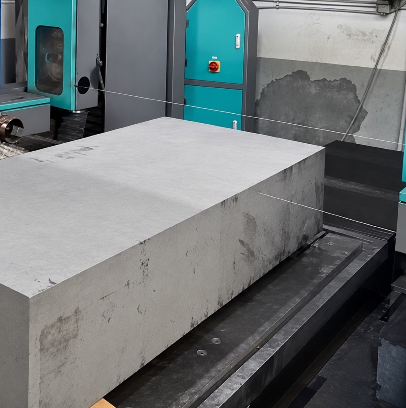
Measure the blank where the drawing and receiving fixture require it. Record thickness distribution, relevant face relationships and edge condition separately. A visual surface check should not be converted into a numerical roughness or flatness result.
Explain the inspection support and orientation. If the blank is moved to a different support for measurement, preserve that detail so a later difference is not automatically attributed to the cutting process. Identify the surfaces used as references rather than calling every face a datum.
NIST’s uncertainty analysis guidance supports matching the measurement to the acceptance decision. More display digits do not establish that a shop-floor method resolves the required feature throughout a large blank.
Keep this inspection attached to the blank identity. The receiving operation needs the individual results and remaining allowances, not merely a message that the slab was cut successfully.
Field Notes: A Bar Trial Cannot Certify a Slab Route
Le documented isostatic graphite trial produced one nominal 500 × 87 × 70 mm bar on an SVI250-80. Reported thickness readings ranged from 69.90 to 70.10 mm; width readings increased from 87.00 to 87.30 mm with wire-diameter compensation disabled.
Those readings show why individual positions and settings matter to a blank handover. They do not establish SHG slab thickness, support behavior or the condition of a plate after removal. The available record is a different machine and workpiece geometry.
No SHG trial containing the full slab support arrangement, cut-off sequence and post-removal measurement map is supplied here. Graphite slab cutting from large blocks therefore remains a route to qualify against the drawing, rather than a measured capability claim inferred from that bar.
Known Limitations / Trade-offs
Graphite slab cutting from large blocks is not complete when the wire exits the material. The blank must be controlled, identified and accepted at the specified stage. Nominal machine capacity does not establish lifting capacity, finished thickness, face accuracy or a universal handling arrangement.
Additional stock can preserve finishing options but consumes material. Reducing stock can improve nominal layout efficiency while leaving insufficient room to correct a face or remove an unacceptable edge. Agree on the trade-off with the next machining operation before finalizing the cut sketch.
Keeping the stock stationary may suit the planned separation route, but quantified handling savings or improved flatness require a matched comparison. Neither the product layout nor the process video supplies that result.
Questions fréquemment posées
What should graphite slab cutting from large blocks prove first?
The trial should show that representative stock can be separated with the proposed support and removal method, leaving a blank that meets the agreed handover requirements. Record the complete sequence and inspection conditions.
Can a good-looking slab go straight to final use?
Only when the drawing and acceptance record permit that delivery state. Otherwise preserve the finishing operations, locating requirements and machining stock in the route. Appearance is a useful observation, but it is not a release certificate.
Does graphite slab cutting from large blocks qualify thin-sheet production?
No. The deliverable and acceptance route must be matched to the trial. A separated slab can be feedstock for another operation without proving the thickness control or handling of thin sheets. Keep the later slicing requirements in the route.
Can wire diameter be used directly as the layout loss?
Do not substitute it for a qualified kerf allowance. The cut sketch should use the measured or otherwise approved separation allowance for the intended process. Where that information is absent, leave the loss term unresolved rather than presenting a calculated recovery figure as validated.
Which support arrangement should be recorded during inspection?
Record how the slab is supported and oriented when the measurements are taken. If that differs from the cutting setup, preserve the distinction. Otherwise a later difference in the readings may be attributed to cutting without evidence that the inspection conditions were comparable.