
On a 500 × 300 mm block of high-purity isotropic graphite, every additional 0.1 mm of kerf across 20 cuts translates to roughly 200 mm³ of unrecoverable material—material you already paid for, and material that shows up as scrap in your monthly cost review. In high-value grades, that is not a rounding error. It is a line item.
Yet most operations trying to reduce kerf loss reach for the wrong lever first. They swap in a thinner cutting tool, run a few test cuts, see a small improvement, and stop. The problem is that tool width is only the visible part of kerf—the rest is process-induced spread that a thinner tool cannot fix by itself, and sometimes makes worse.
This guide walks through the five factors that actually determine kerf loss in graphite cutting: what each one does, how they interact, and where the practical limits are. If you want the broader cost and yield perspective on why kerf matters in the first place, see the Pillar 4 overview on low-kerf graphite cutting. This page is the operational companion.
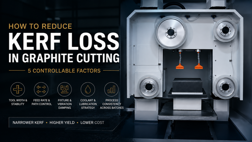
What Determines Kerf Loss in Graphite Cutting
Kerf is the width of material removed by a single cut. In practice, measured kerf is always wider than the nominal tool width, because the cutting process introduces its own contribution—vibration, path deviation, edge chipping, and thermal effects at the cut face. The gap between “tool width” and “measured kerf” is where most of your controllable loss lives.
Reducing kerf loss is therefore not a single-variable problem. It is a system problem. The five factors below are ordered roughly by how often we see them ignored, not by absolute importance. In most graphite operations, batch consistency (Factor 5) delivers more real savings than tool width (Factor 1), even though tool width gets 90% of the attention.
Factor 1: Cutting Tool Width and Stability
Tool width matters, but stability during the cut matters more. A 0.20 mm cutting tool that deflects to an effective 0.28 mm under load produces the same kerf as a 0.28 mm tool that stays straight—except the “thin and unstable” version usually has worse edge quality and shorter tool life.
When evaluating a cutting tool for kerf performance, look at three specifications together, not one:
- Nominal width (the number on the spec sheet)
- Deflection under working load (rarely on the spec sheet—ask, or test)
- Wear pattern over service life (does the tool widen uniformly, or does it develop uneven zones?)
The common mistake is to select the tool with the narrowest nominal width and assume kerf follows. It does not. A tool with 15% wider nominal width but half the deflection can produce a narrower and more consistent kerf across a full production run.
A practical rule from operations: if you cannot measure your tool’s deflection under working conditions, you should not assume it matches the spec sheet. Deflection data from a bench test at room temperature tells you very little about behavior during a two-hour cut on a warm machine.
Factor 2: Feed Rate and Cutting Path Control
Feed rate has a non-linear relationship with kerf. Push too slow and you build up heat, which widens the effective kerf through thermal spread. Push too fast and you introduce vibration and edge chipping, which also widens kerf. The optimum is a band, not a point.
Path control is the less obvious half of this factor. Even at optimal feed, a cutting path that oscillates laterally by ±0.05 mm produces an effective kerf that is 0.1 mm wider than the tool—regardless of how narrow the tool actually is. In long cuts on large graphite blocks, path deviation is often the single largest contributor to kerf loss.
Diagnostic sequence when kerf is drifting:
- Measure kerf at the start, middle, and end of a single cut
- If kerf widens toward the end → thermal drift, reduce feed rate or improve cooling
- If kerf varies mid-cut without a trend → path stability issue, check machine rigidity and any lateral load
- If kerf is uniform per cut but drifts across a batch → tool wear or fixture shift (see Factors 3 and 5)
This sequence takes 20 minutes on the shop floor. Skipping it and instead spending three days evaluating new tools is a common mistake.
Factor 3: Material Fixture and Vibration Damping
Graphite is stiff but brittle. A fixture that cannot suppress workpiece vibration during the cut will produce kerf variation that no tool selection can compensate for. In our experience, fixture-induced kerf noise is roughly 2–3× more common than tool-related kerf variation, and it is almost never the first thing operations check.
The fixture failure modes worth watching:
- Insufficient clamping stiffness on large blocks—the block flexes microscopically against the cut and the kerf tracks the flex
- Point-load clamping rather than distributed clamping, which allows local rotation
- Fixture wear over time—clamping surfaces develop marks and lose contact area, which increases with fixture age
For small parts, the reverse problem appears: excessive clamping force can locally deform soft graphite grades, again shifting the effective kerf. There is no single “right” clamping force—it depends on part geometry, graphite grade, and the cutting direction relative to the material grain.
If you inherit a fixture with a job, do not assume it is optimized. Run a kerf comparison against a temporary rigid setup before accepting the fixture’s performance as baseline.
Factor 4: Coolant and Lubrication Strategy
Coolant does two things for kerf control: it removes heat that would otherwise widen the effective cut through thermal expansion, and it flushes cutting debris that would otherwise re-enter the kerf and widen it through secondary abrasion.
Dry cutting is possible for graphite and is often used for cleanliness reasons—the resulting powder is easier to collect than a slurry. But dry cutting almost always produces measurably wider kerf than wet cutting on the same material, typically by 5–15% depending on cut length and speed. If your operation is dry for downstream contamination reasons, that trade-off is legitimate. If it is dry because “graphite doesn’t need coolant,” you are paying for that assumption in kerf.
For wet cutting, the two common mistakes are:
- クーラントの流路方向の間違い 切断パスに対して—フローがカーフからデブリをクリアしない場合、デブリがカーフの表面を再切断します
- 不十分な流量 切断深さに対して—クーラントは作業ゾーンに到達する必要があり、単にその近くにスプレーするだけでは不十分です
クーラントの選択自体は、ほとんどの人が考えるよりも重要ではありません。フローと方向が正しければ。私たちが目にするほとんどの操作は、不十分な供給で十分なクーラントを実行しています。.
要因5:バッチ間のプロセスの整合性
これは、ほとんどの操作が最後に発見する要因であり、通常は最も多くの節約をもたらす要因です。平均カーフを10%削減することは価値があります。100個の部品のバッチ全体でカーフの標準偏差を30%削減することは、スクラップ率の低下と下流のネストのタイト化に直接つながるため、はるかに価値があります。.
バッチ全体でのカーフのドリフトは、3つのソースから発生します。
- 工具摩耗—切削工具は徐々に、予測可能に広がります
- 固定具のドリフト—固定具が暖まると、クランプ面が微量のシフトをします
- クーラントの劣化—切削液がデブリを拾い、その効果的な冷却が変化します
正しい対応は、カーフに影響を与え始めた瞬間に各ソースを個別に「修正」することではありません。それは負けゲームです。正しい対応は、 ドリフトを許容するプロセスを構築することです 次の方法で:
- バッチの部品1でカーフのベースラインを確立する
- N個の部品ごとにカーフをサンプリングする(通常はバッチサイズに応じて10〜20個ごと)
- アクション(工具交換、クーラント補充、または固定具チェック)をトリガーするドリフトしきい値を設定する
- 各トリガーがいつ発火したかを文書化し、実際のドリフト率のデータセットを構築します
このガイド全体から1つだけ実装する時間がある場合は、ステップ3—定義されたドリフトしきい値と文書化された応答を実装してください。これだけでも、通常は工具交換よりもバッチレベルのカーフ変動を削減します。.
バッチ整合性が収率数にどのように変換されるかについての詳細については、収率に焦点を当てたコンパニオンページを参照してください。 グラファイト切断収率の向上.
測定するものとカーフ削減の追跡方法
有用なカーフのベースラインを確立するために、座標測定機や光学式輪郭測定機は必要ありません。ほとんどのグラファイト操作では、キャリブレーションされたデジタルノギスまたは低コストの光学コンパレーターで十分です。ただし、一貫して測定することが前提です。.
追跡する価値のある3つのメトリック:
- カットあたりの平均カーフ—単一のカット全体の平均幅
- カット内のカーフ標準偏差—カーフが長さに沿ってどの程度変動するか
- バッチカーフ標準偏差—バッチ全体で平均カーフが部品ごとにどの程度変動するか
これらの3つの数値を工具の寿命、クーラントの寿命、およびプロセスの変更に対してプロットした週次のレビューは、多数の追加メトリックの月次レビューよりも価値があります。複雑さがカーフを改善するわけではありません。一貫した測定が重要です。.
実用的な提案:カーフをデータベースだけでなく、ウォールチャートで追跡します。ショップフロアの目に見えるチャートは、データベースレポートとは異なる方法でオペレーターの行動を変えます。測定規律は、目に見えるようになると自己強化されます。.
低いカーフを追いかけるべきではないとき
すべてのグラファイト操作が積極的なカーフ削減の恩恵を受けるわけではありません。部品コストが下流の加工時間によって支配されており、部品あたりの材料費が総コストのごく一部である場合、カーフを20%削減しても、総コストは2〜3%しか削減されない可能性があります。それは現実ですが、プロセスの投資に見合う価値がないかもしれません。.
重大なカーフ削減の恩恵を受ける操作には、3つの共通の特徴があります。
- 材料費が総部品コストのかなりの部分を占める(通常は30%以上)
- バッチサイズが大きく、整合性が重要である
- 下流のプロセスでは、カーフの変動から簡単に回復できない(つまり、許容できる仕上げステップがない)
これらすべてに一致する場合は、このガイドの要因が直接適用されます。1つにしか一致しない場合は、カーフ削減に投資する額と、他の収率レバーに投資する額を慎重に検討してください。.
関連記事
- 低カーフグラファイト切断:材料損失、歩留まり、および製造コストへの影響 —カーフがなぜ重要なのかについてのコストと経済的な視点
- グラファイト切断収率の向上 —カーフ制御が全体的な収率パフォーマンスにどのように関連するか
- グラファイト加工における材料損失 —加工におけるカーフ損失と切りくず除去の比較
- 精密グラファイトスライシング —高精度スライスアプリケーション向けの関連プロセス


