
On a 500 × 300 mm block of high-purity isotropic graphite, every additional 0.1 mm of kerf across 20 cuts translates to roughly 200 mm³ of unrecoverable material—material you already paid for, and material that shows up as scrap in your monthly cost review. In high-value grades, that is not a rounding error. It is a line item.
Yet most operations trying to reduce kerf loss reach for the wrong lever first. They swap in a thinner cutting tool, run a few test cuts, see a small improvement, and stop. The problem is that tool width is only the visible part of kerf—the rest is process-induced spread that a thinner tool cannot fix by itself, and sometimes makes worse.
This guide walks through the five factors that actually determine kerf loss in graphite cutting: what each one does, how they interact, and where the practical limits are. If you want the broader cost and yield perspective on why kerf matters in the first place, see the Pillar 4 overview on low-kerf graphite cutting. This page is the operational companion.
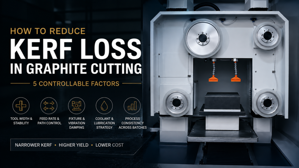
What Determines Kerf Loss in Graphite Cutting
Kerf is the width of material removed by a single cut. In practice, measured kerf is always wider than the nominal tool width, because the cutting process introduces its own contribution—vibration, path deviation, edge chipping, and thermal effects at the cut face. The gap between “tool width” and “measured kerf” is where most of your controllable loss lives.
Reducing kerf loss is therefore not a single-variable problem. It is a system problem. The five factors below are ordered roughly by how often we see them ignored, not by absolute importance. In most graphite operations, batch consistency (Factor 5) delivers more real savings than tool width (Factor 1), even though tool width gets 90% of the attention.
Factor 1: Cutting Tool Width and Stability
Tool width matters, but stability during the cut matters more. A 0.20 mm cutting tool that deflects to an effective 0.28 mm under load produces the same kerf as a 0.28 mm tool that stays straight—except the “thin and unstable” version usually has worse edge quality and shorter tool life.
When evaluating a cutting tool for kerf performance, look at three specifications together, not one:
- Nominal width (the number on the spec sheet)
- Deflection under working load (rarely on the spec sheet—ask, or test)
- Wear pattern over service life (does the tool widen uniformly, or does it develop uneven zones?)
The common mistake is to select the tool with the narrowest nominal width and assume kerf follows. It does not. A tool with 15% wider nominal width but half the deflection can produce a narrower and more consistent kerf across a full production run.
A practical rule from operations: if you cannot measure your tool’s deflection under working conditions, you should not assume it matches the spec sheet. Deflection data from a bench test at room temperature tells you very little about behavior during a two-hour cut on a warm machine.
Factor 2: Feed Rate and Cutting Path Control
Feed rate has a non-linear relationship with kerf. Push too slow and you build up heat, which widens the effective kerf through thermal spread. Push too fast and you introduce vibration and edge chipping, which also widens kerf. The optimum is a band, not a point.
Path control is the less obvious half of this factor. Even at optimal feed, a cutting path that oscillates laterally by ±0.05 mm produces an effective kerf that is 0.1 mm wider than the tool—regardless of how narrow the tool actually is. In long cuts on large graphite blocks, path deviation is often the single largest contributor to kerf loss.
Diagnostic sequence when kerf is drifting:
- Measure kerf at the start, middle, and end of a single cut
- If kerf widens toward the end → thermal drift, reduce feed rate or improve cooling
- If kerf varies mid-cut without a trend → path stability issue, check machine rigidity and any lateral load
- If kerf is uniform per cut but drifts across a batch → tool wear or fixture shift (see Factors 3 and 5)
This sequence takes 20 minutes on the shop floor. Skipping it and instead spending three days evaluating new tools is a common mistake.
Factor 3: Material Fixture and Vibration Damping
Graphite is stiff but brittle. A fixture that cannot suppress workpiece vibration during the cut will produce kerf variation that no tool selection can compensate for. In our experience, fixture-induced kerf noise is roughly 2–3× more common than tool-related kerf variation, and it is almost never the first thing operations check.
The fixture failure modes worth watching:
- Insufficient clamping stiffness on large blocks—the block flexes microscopically against the cut and the kerf tracks the flex
- Point-load clamping rather than distributed clamping, which allows local rotation
- Fixture wear over time—clamping surfaces develop marks and lose contact area, which increases with fixture age
For small parts, the reverse problem appears: excessive clamping force can locally deform soft graphite grades, again shifting the effective kerf. There is no single “right” clamping force—it depends on part geometry, graphite grade, and the cutting direction relative to the material grain.
If you inherit a fixture with a job, do not assume it is optimized. Run a kerf comparison against a temporary rigid setup before accepting the fixture’s performance as baseline.
Factor 4: Coolant and Lubrication Strategy
Coolant does two things for kerf control: it removes heat that would otherwise widen the effective cut through thermal expansion, and it flushes cutting debris that would otherwise re-enter the kerf and widen it through secondary abrasion.
Dry cutting is possible for graphite and is often used for cleanliness reasons—the resulting powder is easier to collect than a slurry. But dry cutting almost always produces measurably wider kerf than wet cutting on the same material, typically by 5–15% depending on cut length and speed. If your operation is dry for downstream contamination reasons, that trade-off is legitimate. If it is dry because “graphite doesn’t need coolant,” you are paying for that assumption in kerf.
For wet cutting, the two common mistakes are:
- Hướng dòng chảy chất làm mát sai tương ứng với đường cắt—nếu dòng chảy không loại bỏ cặn bẩn khỏi rãnh cắt, cặn bẩn sẽ cắt lại bề mặt rãnh cắt
- Tốc độ dòng chảy không đủ cho độ sâu cắt—chất làm mát cần tiếp cận vùng làm việc, không chỉ phun gần đó
Bản thân việc lựa chọn chất làm mát ít quan trọng hơn hầu hết mọi người nghĩ, một khi bạn đã có dòng chảy và hướng đi đúng. Hầu hết các hoạt động chúng tôi thấy đều đang sử dụng chất làm mát đầy đủ với việc cung cấp không đầy đủ.
Yếu tố 5: Tính nhất quán của quy trình giữa các lô
Đây là yếu tố mà hầu hết các hoạt động phát hiện ra cuối cùng, và thường là yếu tố mang lại nhiều khoản tiết kiệm nhất. Giảm rãnh cắt trung bình 10% là có giá trị. Giảm độ lệch chuẩn rãnh cắt trong một lô 100 chi tiết 30% có giá trị hơn đáng kể, vì nó trực tiếp chuyển thành tỷ lệ phế liệu thấp hơn và việc xếp chồng các chi tiết ở các công đoạn sau chặt chẽ hơn.
Sự trôi dạt rãnh cắt trong một lô đến từ ba nguồn:
- Sự hao mòn của dụng cụ— dụng cụ cắt dần dần và có thể dự đoán được làm rộng ra
- Sự trôi dạt của bộ gá— các bề mặt kẹp dịch chuyển những lượng rất nhỏ khi bộ gá nóng lên
- Sự suy giảm chất làm mát— chất lỏng cắt lấy cặn bẩn và khả năng làm mát hiệu quả của nó thay đổi
Phản ứng đúng đắn không phải là “sửa chữa” từng nguồn riêng lẻ ngay khi nó bắt đầu ảnh hưởng đến rãnh cắt. Đó là một cuộc chiến thua. Phản ứng đúng đắn là xây dựng một quy trình chấp nhận sự trôi dạt bằng cách:
- Thiết lập một đường cơ sở rãnh cắt trên Chi tiết 1 của lô
- Lấy mẫu rãnh cắt sau mỗi N chi tiết (thường là mỗi 10–20 tùy thuộc vào kích thước lô)
- Đặt một ngưỡng trôi dạt kích hoạt hành động (thay đổi dụng cụ, làm mới chất làm mát hoặc kiểm tra bộ gá)
- Ghi lại thời điểm mỗi ngưỡng được kích hoạt, để bạn xây dựng một bộ dữ liệu về tốc độ trôi dạt trong thực tế
Nếu bạn chỉ có thời gian để thực hiện một điều từ toàn bộ hướng dẫn này, hãy thực hiện bước 3—một ngưỡng trôi dạt được xác định và một phản ứng được ghi lại. Chỉ riêng điều này thường làm giảm sự biến động rãnh cắt ở cấp độ lô nhiều hơn bất kỳ lần thay đổi dụng cụ nào.
Để có cái nhìn sâu hơn về cách tính nhất quán của lô chuyển thành số lượng sản phẩm, hãy xem trang đồng hành tập trung vào sản lượng về cải thiện sản lượng cắt than chì.
Đo lường và Theo dõi Giảm Rãnh cắt như thế nào
Bạn không cần máy đo tọa độ hoặc máy đo biên dạng quang học để thiết lập các đường cơ sở rãnh cắt hữu ích. Một thước cặp kỹ thuật số được hiệu chuẩn hoặc một máy đo biên dạng quang học chi phí thấp là đủ cho hầu hết các hoạt động than chì, miễn là bạn đo lường nhất quán.
Ba chỉ số đáng theo dõi:
- Rãnh cắt trung bình trên mỗi lần cắt— chiều rộng trung bình trên một lần cắt duy nhất
- Độ lệch chuẩn rãnh cắt trong một lần cắt— rãnh cắt thay đổi bao nhiêu dọc theo chiều dài
- Độ lệch chuẩn rãnh cắt của lô— độ rộng rãnh cắt trung bình thay đổi bao nhiêu từ chi tiết này sang chi tiết khác trong một lô
Một đánh giá hàng tuần về ba con số này, được vẽ biểu đồ theo tuổi dụng cụ, tuổi chất làm mát và bất kỳ thay đổi quy trình nào, có giá trị hơn một đánh giá hàng tháng về hàng tá chỉ số bổ sung. Sự phức tạp không phải là thứ cải thiện rãnh cắt. Sự đo lường nhất quán mới là thứ cải thiện.
Một gợi ý thực tế: theo dõi rãnh cắt trên biểu đồ treo tường, không chỉ trong cơ sở dữ liệu. Một biểu đồ hiển thị trên sàn xưởng thay đổi hành vi của người vận hành theo cách mà báo cáo cơ sở dữ liệu không làm được. Kỷ luật đo lường tự củng cố khi nó hiển thị.
Khi nào không nên theo đuổi việc giảm rãnh cắt
Không phải mọi hoạt động than chì đều có lợi từ việc giảm rãnh cắt mạnh mẽ. Nếu chi phí chi tiết của bạn chủ yếu là thời gian gia công ở các công đoạn sau, và chi phí vật liệu trên mỗi chi tiết chỉ chiếm một phần nhỏ trong tổng chi phí, thì việc giảm rãnh cắt 20% có thể chỉ giảm tổng chi phí 2–3%. Điều đó là có thật, nhưng có thể không biện minh cho việc đầu tư vào quy trình.
Các hoạt động có lợi nhất từ việc giảm rãnh cắt nghiêm túc có ba đặc điểm chung:
- Chi phí vật liệu chiếm một phần đáng kể trong tổng chi phí chi tiết (thường là 30%+)
- Kích thước lô đủ lớn để tính nhất quán quan trọng
- Các quy trình ở các công đoạn sau không thể dễ dàng khắc phục sự biến đổi rãnh cắt (tức là, không có bước hoàn thiện dung sai)
Nếu bạn đáp ứng cả ba, các yếu tố của hướng dẫn này sẽ áp dụng trực tiếp. Nếu bạn chỉ đáp ứng một, hãy cẩn thận về mức độ bạn đầu tư vào việc giảm rãnh cắt so với các đòn bẩy sản lượng khác.
Đọc thêm
- Cắt Graphite Kerf Thấp: Tổn thất Vật liệu, Năng suất và Tác động Chi phí Sản xuất — góc nhìn chi phí và kinh tế về lý do tại sao rãnh cắt lại quan trọng
- Cải thiện Sản lượng Cắt Than Chì — cách kiểm soát rãnh cắt kết nối với hiệu suất sản lượng tổng thể
- Sự hao hụt vật liệu trong quá trình gia công than chì — so sánh tổn thất rãnh cắt với việc loại bỏ phoi trong gia công
- Precision Graphite Slicing — quy trình liên quan cho các ứng dụng cắt lát có độ chính xác cao


