最適化する前に、グラファイトスライシングプロセスを理解することが不可欠です。ワイヤー速度、送り速度、張力、クーラント流量など、すべてのパラメータが最終結果に影響します。プロセスを正しく行えば、一貫した厚さ、きれいなエッジ、最小限の無駄でプレートを製造できます。間違えれば、欠け、厚さのばらつき、スクラップに対処することになります。.
この記事では、生のブロックから完成したプレートまでの完全なグラファイトスライシングプロセスを、各段階、重要な変数、およびほとんどの問題が発生する場所を網羅して解説します。.

グラファイトスライシングとは?
グラファイトスライシングとは、精密な切断方法、最も一般的にはダイヤモンドワイヤーソーイングを使用して、グラファイトブロックをより薄いプレートまたはウェーハに切断するプロセスです。材料をフライス加工で除去するCNC加工とは異なり、スライシングは材料の除去を最小限に抑えてブロックを平面に沿って分離します。.
この区別は、1つの重要な理由で重要です。 スライシングは材料を保存し、機械加工は材料を消費します。. ケフが0.5 mmのダイヤモンドワイヤーは、ブロックの30〜50%を粉塵やチップに変換するCNCエンドミルよりもはるかに少ないグラファイトを無駄にします。.
グラファイトスライシングプロセスは、以下を製造するために使用されます。
- 燃料電池およびフロー電池用バイポーラプレート
- EDM電極ブランク
- 半導体処理コンポーネント(ウェーハチャック、サセプター)
- ヒートスプレッダーおよび熱管理プレート
- 高温炉用発熱体
グラファイトスライシングプロセスの5つの段階
ステージ1 — ブロックの準備と取り付け
切断が始まる前に、グラファイトブロックを適切に準備する必要があります。
Inspection. Check the block for visible cracks, voids, or density variations. Isostatic-pressed graphite is more uniform than extruded or molded grades, but defects still occur. Cutting through a hidden void wastes the entire slice.
Dimensioning. Measure the block precisely. The slicing plan — how many plates, what thickness, what kerf allowance — determines total material yield. A well-planned slicing layout on a 300 × 200 × 100 mm block can recover 85–90% of the material as usable plates. A poorly planned one recovers 70% or less.
Mounting. The block is fixtured on the machine’s work table using either mechanical clamping or adhesive bonding. The mounting must be rigid — any movement during cutting translates directly into thickness variation and parallelism errors.
Stage 2 — Wire Setup and Tensioning
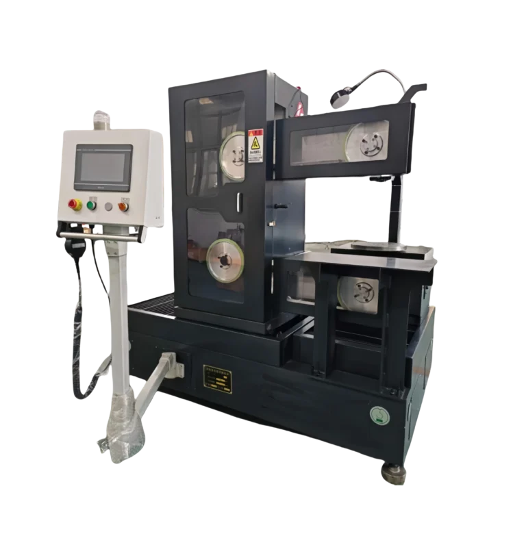
Diamond wire is the cutting tool. The graphite slicing process uses a closed-loop diamond wire that circulates continuously through the cut zone.
Wire selection. Wire diameter typically ranges from 0.3–0.65 mm depending on the required kerf width and plate thickness. Thinner wire = narrower kerf = less waste, but also lower rigidity and higher breakage risk.
| ワイヤー径 | Typical Kerf | 最適 |
|---|---|---|
| 0.3–0.4 mm | 0.4–0.5 mm | Thin plates (≤ 3 mm), high-value graphite |
| 0.4–0.5 mm | 0.5–0.6 mm | General purpose slicing |
| 0.5–0.65 mm | 0.6–0.8 mm | Thick plates, high feed rates |
Tension. Wire tension affects cut straightness and surface quality. Too low → wire wanders, causing wavy cuts. Too high → wire fatigue and premature breakage. Servo-controlled tension systems maintain consistent force throughout the cut, compensating for wire stretch and thermal expansion.
Stage 3 — Cutting Parameters
This is where the graphite slicing process either succeeds or produces scrap. Three variables interact:
ワイヤースピード controls how fast the diamond abrasive moves across the graphite surface. Higher speed = faster material removal but more heat generation. For graphite, typical wire speeds range from 20–60 m/s. Graphite’s relatively soft structure (compared to silicon or germanium) allows higher speeds than many other precision materials.
送り速度 is how fast the block moves into the wire. This is the primary control for throughput vs. quality:
| フィード・レート | 結果 | Trade-off |
|---|---|---|
| Low (2–5 mm/min) | Smooth surface, tight tolerance | Slower production |
| Medium (5–15 mm/min) | 良いバランス | Standard production |
| High (15–30 mm/min) | Fast production | Risk of chipping, wider kerf |
Coolant delivery. The graphite slicing process generates fine particles that must be flushed from the cut zone continuously. Coolant (typically water-based for graphite, unlike the mineral oil used for germanium or silicon) serves three functions:
- Removes cutting debris from the kerf
- Reduces friction between wire and graphite
- Controls temperature at the cut interface
Insufficient coolant flow is the most common cause of surface defects in graphite slicing. When debris accumulates in the kerf, it re-cuts the freshly exposed surface, creating scratches and increasing roughness.

Stage 4 — Monitoring and In-Process Adjustment
Modern diamond wire saws provide real-time feedback on:
- Wire tension (detects wire fatigue or obstruction)
- Feed force (indicates cutting resistance changes)
- Wire speed (confirms consistent abrasive delivery)
The graphite slicing process is more forgiving than slicing harder materials like silicon carbide or sapphire. But graphite’s porous structure creates a unique challenge: density variations within the block change cutting resistance mid-slice. A zone of higher density slows the cut and increases wire deflection. Without monitoring, this produces a plate that’s thicker on one side — a flatness and parallelism problem that can’t be fixed without grinding away material.
Adaptive feed control — automatically reducing feed rate when cutting resistance increases — is the most effective solution.
Stage 5 — Separation, Cleaning, and Inspection
After cutting:
Separation. The sliced plate is carefully removed from the remaining block. For thin plates (< 2 mm), this step requires care to avoid cracking.
Cleaning. Graphite slurry (coolant + cutting debris) must be thoroughly removed. Residual graphite particles on the surface can contaminate downstream processes, especially in semiconductor applications.
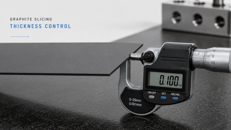
Inspection. Key measurements include:
- Thickness at multiple points (verifies thickness control)
- Surface roughness (Ra)
- Edge condition (checks for chipping and defects)
- Flatness and parallelism
Graphite Slicing Process vs. CNC Machining: Key Differences
| 要因 | Diamond Wire Slicing | CNC Machining |
|---|---|---|
| Material removal | Kerf only (0.4–0.8 mm) | 30–50% of block becomes chips |
| 粉塵の発生 | Minimal (wet process) | Heavy (requires extraction) |
| Surface stress | 低い | Higher (tool pressure) |
| Achievable thickness | Down to 0.5 mm | Practical limit ~3 mm |
| Complex geometries | Limited to planar cuts | Unlimited |
| Setup time | Minutes | Hours (fixturing, tooling) |
For a deeper comparison of when each method makes sense, see our guide on グラファイト切断と機械加工.
Neither method is universally better. The graphite slicing process excels at producing flat plates from blocks with maximum material recovery. CNC machining is necessary for 3D geometries, pockets, and features that slicing can’t create. Many manufacturers use both — slicing for blank preparation, machining for final features.
Common Graphite Slicing Process Mistakes
1. Ignoring graphite grade differences. Isostatic graphite (grain size < 10 μm) slices cleanly. Extruded graphite (grain size 50–200 μm) is more prone to edge chipping and breakage. The same cutting parameters don’t work for both.
2. Running dry or with insufficient coolant. Graphite dust is abrasive. Without adequate coolant, it acts as a secondary abrasive between wire and workpiece, degrading surface quality and accelerating wire wear.
3. Skipping block inspection. A hidden crack or void in the block can cause the plate to fracture during or after slicing. Two minutes of visual and dimensional inspection saves hours of rework.
4. Using wrong wire diameter for the job. Thin wire on thick blocks = excessive wire deflection and poor dimensional accuracy. Thick wire on thin plates = excessive kerf loss relative to plate thickness.
Getting the Graphite Slicing Process Right
The graphite slicing process is fundamentally simple — a diamond wire moves through a graphite block. But the difference between a good process and a poor one shows up in yield, surface quality, and downstream processing costs.
The key is matching three things:
- Wire selection to your graphite grade and plate thickness
- Cutting parameters to your quality requirements
- Coolant delivery to your cutting speed
For an overview of how slicing fits into a complete 精密グラファイトスライス workflow — including thickness control, defect prevention, and yield optimization — see our pillar guide.