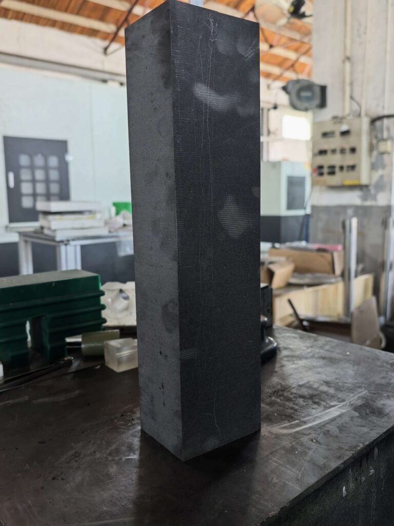
Understanding the graphite slicing process is essential before you can optimize it. Every parameter — wire speed, feed rate, tension, coolant flow — affects the final result. Get the process right, and you produce plates with consistent thickness, clean edges, and minimal waste. Get it wrong, and you’re dealing with chipping, thickness variation, and scrap.
This article breaks down the complete graphite slicing process from raw block to finished plate, covering each stage, the variables that matter, and where most problems originate.
What Is Graphite Slicing?
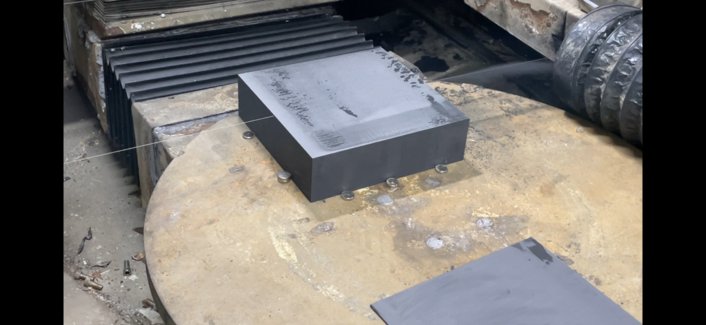
Graphite slicing is the process of cutting a graphite block into thinner plates or wafers using a precision cutting method — most commonly diamond wire sawing. Unlike CNC machining, which removes material by milling, slicing separates the block along a plane with minimal material removal.
The distinction matters for one critical reason: slicing preserves material, machining consumes it. A diamond wire with a 0.5 mm kerf wastes far less graphite than a CNC end mill that converts 30–50% of the block into dust and chips.
The graphite slicing process is used to produce:
- Bipolar plates for fuel cells and flow batteries
- EDM electrode blanks
- Semiconductor processing components (wafer chucks, susceptors)
- Heat spreaders and thermal management plates
- Heating elements for high-temperature furnaces
The 5 Stages of the Graphite Slicing Process
Stage 1 — Block Preparation and Mounting
Before any cutting begins, the graphite block must be properly prepared:
Inspection. Check the block for visible cracks, voids, or density variations. Isostatic-pressed graphite is more uniform than extruded or molded grades, but defects still occur. Cutting through a hidden void wastes the entire slice.
Dimensioning. Measure the block precisely. The slicing plan — how many plates, what thickness, what kerf allowance — determines total material yield. A well-planned slicing layout on a 300 × 200 × 100 mm block can recover 85–90% of the material as usable plates. A poorly planned one recovers 70% or less.
Mounting. Блок закрепляется на рабочем столе станка с помощью механического зажима или клеевого соединения. Крепление должно быть жестким — любое смещение во время резки приводит к изменению толщины и ошибкам параллельности.
Stage 2 — Wire Setup and Tensioning
Diamond wire is the cutting tool. The graphite slicing process uses a closed-loop diamond wire that circulates continuously through the cut zone.
Wire selection. Wire diameter typically ranges from 0.3–0.65 mm depending on the required kerf width and plate thickness. Thinner wire = narrower kerf = less waste, but also lower rigidity and higher breakage risk.
| Диаметр проволоки | Typical Kerf | Лучшее для |
|---|---|---|
| 0.3–0.4 mm | 0.4–0.5 mm | Thin plates (≤ 3 mm), high-value graphite |
| 0.4–0.5 mm | 0.5–0.6 mm | General purpose slicing |
| 0.5–0.65 mm | 0.6–0.8 mm | Thick plates, high feed rates |
Tension. Wire tension affects cut straightness and surface quality. Too low → wire wanders, causing wavy cuts. Too high → wire fatigue and premature breakage. Servo-controlled tension systems maintain consistent force throughout the cut, compensating for wire stretch and thermal expansion.
Stage 3 — Cutting Parameters
This is where the graphite slicing process either succeeds or produces scrap. Three variables interact:
Скорость движения проволоки controls how fast the diamond abrasive moves across the graphite surface. Higher speed = faster material removal but more heat generation. For graphite, typical wire speeds range from 20–60 m/s. Graphite’s relatively soft structure (compared to silicon or germanium) allows higher speeds than many other precision materials.
Скорость подачи is how fast the block moves into the wire. This is the primary control for throughput vs. quality:
| Скорость подачи | Result | Trade-off |
|---|---|---|
| Low (2–5 mm/min) | Smooth surface, tight tolerance | Slower production |
| Medium (5–15 mm/min) | Good balance | Standard production |
| High (15–30 mm/min) | Fast production | Risk of chipping, wider kerf |
Coolant delivery. The graphite slicing process generates fine particles that must be flushed from the cut zone continuously. Coolant (typically water-based for graphite, unlike the mineral oil used for germanium or silicon) serves three functions:
- Removes cutting debris from the kerf
- Reduces friction between wire and graphite
- Controls temperature at the cut interface
Insufficient coolant flow is the most common cause of surface defects in graphite slicing. When debris accumulates in the kerf, it re-cuts the freshly exposed surface, creating scratches and increasing roughness.
Stage 4 — Monitoring and In-Process Adjustment
Modern diamond wire saws provide real-time feedback on:
- Wire tension (detects wire fatigue or obstruction)
- Feed force (indicates cutting resistance changes)
- Wire speed (confirms consistent abrasive delivery)
The graphite slicing process is more forgiving than slicing harder materials like silicon carbide or sapphire. But graphite’s porous structure creates a unique challenge: density variations within the block change cutting resistance mid-slice. A zone of higher density slows the cut and increases wire deflection. Without monitoring, this produces a plate that’s thicker on one side — a flatness and parallelism problem that can’t be fixed without grinding away material.
Adaptive feed control — automatically reducing feed rate when cutting resistance increases — is the most effective solution.
Stage 5 — Separation, Cleaning, and Inspection
After cutting:
Separation. The sliced plate is carefully removed from the remaining block. For thin plates (< 2 mm), this step requires care to avoid cracking.
Cleaning. Graphite slurry (coolant + cutting debris) must be thoroughly removed. Residual graphite particles on the surface can contaminate downstream processes, especially in semiconductor applications.
Inspection. Key measurements include:
- Толщина в нескольких точках (проверяет контроль толщины)
- Surface roughness (Ra)
- Edge condition (checks for chipping and defects)
- Flatness and parallelism
Graphite Slicing Process vs. CNC Machining: Key Differences
| Factor | Diamond Wire Slicing | CNC Machining |
|---|---|---|
| Material removal | Kerf only (0.4–0.8 mm) | 30–50% of block becomes chips |
| Образование пыли | Minimal (wet process) | Heavy (requires extraction) |
| Surface stress | Низкий | Higher (tool pressure) |
| Achievable thickness | Down to 0.5 mm | Практический предел ~3 мм |
| Сложные геометрии | Ограничено плоскими разрезами | Неограниченно |
| Время настройки | Минуты | Часы (оснастка, инструменты) |
Для более глубокого сравнения того, когда каждый метод имеет смысл, см. наше руководство по резка графита против механической обработки.
Ни один метод не является универсально лучшим. Процесс нарезки графита отлично подходит для изготовления плоских пластин из блоков с максимальным восстановлением материала. Обработка на станках с ЧПУ необходима для 3D-геометрий, карманов и элементов, которые не могут быть созданы нарезкой. Многие производители используют оба метода — нарезку для подготовки заготовок, механическую обработку для окончательных элементов.
Распространенные ошибки в процессе нарезки графита
1. Игнорирование различий в марках графита. Изостатический графит (размер зерна < 10 мкм) нарезается чисто. Экструдированный графит (размер зерна 50–200 мкм) более склонен к сколам и поломке краев. Одни и те же параметры резки не подходят для обоих.
2. Работа всухую или с недостаточным охлаждением. Графитовая пыль абразивна. Без адекватного охлаждения она действует как вторичный абразив между проволокой и заготовкой, ухудшая качество поверхности и ускоряя износ проволоки.
3. Пропуск проверки блока. Скрытый трещина или пустота в блоке может привести к разрушению пластины во время или после нарезки. Две минуты визуального и размерного контроля экономят часы переделок.
4. Using wrong wire diameter for the job. Тонкая проволока на толстых блоках = чрезмерное отклонение проволоки и низкая точность размеров. Толстая проволока на тонких пластинах = чрезмерные потери на пропил относительно толщины пластины.
Getting the Graphite Slicing Process Right
The graphite slicing process is fundamentally simple — a diamond wire moves through a graphite block. But the difference between a good process and a poor one shows up in yield, surface quality, and downstream processing costs.
The key is matching three things:
- Wire selection to your graphite grade and plate thickness
- Cutting parameters to your quality requirements
- Coolant delivery to your cutting speed
For an overview of how slicing fits into a complete прецизионная нарезка графита workflow — including thickness control, defect prevention, and yield optimization — see our pillar guide.