Графитовая пластина может идеально соответствовать целевой толщине — 5,00 мм в каждой точке измерения — и при этом быть непригодной. Как? Если пластина изогнута, имеет форму чаши или клиновидная, она не будет плотно прилегать к сопрягаемой поверхности. Последующая сборка выходит из строя, ухудшается тепловой контакт, и пластина бракуется.
Плоскостность и параллельность при резке графита — это геометрические показатели качества, которые определяют, будет ли нарезанная пластина фактически функционировать в предполагаемом применении. Толщина показывает, насколько толста пластина. Плоскостность показывает, являются ли поверхности плоскими. Параллельность показывает, равноудалены ли две поверхности в каждой точке.
В этой статье рассматриваются причины ошибок плоскостности и параллельности при резке графита, способы их измерения и минимизации на этапе резки.

Плоскостность и параллельность при резке графита: определения
Эти два термина связаны, но измеряют разные вещи:
Плоскостность — это отклонение одной поверхности от идеальной плоскости. Плоскостность 0,02 мм означает, что вся поверхность находится в пределах зоны толщиной 0,02 мм между двумя параллельными плоскостями. Она описывает, насколько “волнистой” или “изогнутой” является одна сторона пластины.
Параллельность — это отклонение между двумя противоположными поверхностями. Параллельность 0,05 мм означает, что максимальная разница толщин между любыми двумя точками на пластине составляет 0,05 мм. Она описывает, насколько “клиновидной” является пластина.
| Метрика | Что измеряет | Пример спецификации | Влияние |
|---|---|---|---|
| Плоскостность | Планарность одной поверхности | ≤ 0,03 мм на 200 мм | Контакт поверхности, герметизация |
| Параллельность | Равноудаленность двух поверхностей | ≤ 0,05 мм на 200 мм | Stack compression, thermal transfer |
| TTV | Total thickness variation | ≤ 0.05 mm | Combines parallelism + local variation |
A plate with good parallelism can still have poor flatness — both surfaces might be equally curved. And a plate with good flatness on each face can still have poor parallelism if one face was cut at a slight angle to the other.
Why Graphite Slicing Flatness Matters by Application
Different applications have different tolerance requirements:
Fuel Cell Bipolar Plates
Bipolar plates are stacked in compression. If a plate isn’t flat, the gasket doesn’t seal uniformly. If parallelism is off, the compression pressure concentrates on the thicker side, creating uneven contact resistance across the cell. According to the U.S. Department of Energy, bipolar plates account for a significant portion of fuel cell stack cost — geometric rejects directly increase manufacturing cost per kilowatt.
Typical requirement: flatness ≤ 0.03 mm, parallelism ≤ 0.05 mm.
EDM Electrode Blanks
An EDM electrode must be mounted perpendicular to the workpiece. A non-flat electrode base means the electrode sits at an angle in the holder, transferring that angular error to the machined cavity. For precision mold work, this is unacceptable.
Typical requirement: flatness ≤ 0.05 mm, parallelism ≤ 0.08 mm.
Компоненты полупроводниковых процессов
Вафельные патроны, держатели и нагревательные элементы передают геометрию своей поверхности на пластину или подложку. Неплоский патрон приводит к получению неплоской пластины — геометрия распространяется на весь процесс. Ведущие производители полупроводникового оборудования устанавливают требования к плоскостности графитовых компонентов в диапазоне 0,01–0,02 мм.
Типичное требование: плоскостность ≤ 0,02 мм, параллельность ≤ 0,03 мм.
Что вызывает ошибки плоскостности при резке графита
1. Изгиб проволоки во время резки
Наиболее частая причина проблем с плоскостностью. Когда алмазная проволока проходит через графитовый блок, сопротивление резки отталкивает проволоку назад (в направлении, противоположном подаче). Проволока изгибается, и поверхность реза не является идеальной плоскостью — это слегка вогнутая кривая.
Степень изгиба зависит от:
- Скорость подачи — более высокая подача = большее усилие = больший изгиб
- Натяжение проволоки — более низкое натяжение = больший изгиб
- Длина реза — более длинный пролет = больший потенциальный прогиб
- Диаметр проволоки — более тонкая проволока более гибкая и легче изгибается
Рез длиной 300 мм при агрессивных скоростях подачи может привести к образованию поверхности с вогнутостью 0,05–0,1 мм в центре. Проволока фактически провисает в середине реза, прорезая там глубже.
2. Снятие остаточных напряжений
Графитовые блоки — особенно экструдированные и формованные марки — содержат внутренние напряжения от производственного процесса. Когда удаляется слой, напряжения перераспределяются, и пластина может деформироваться или изгибаться после отделения от блока.
Isostatic-pressed graphite has lower internal stress than extruded graphite, which is one reason it’s preferred for precision applications. But even isostatic grades can exhibit measurable warpage in thin plates (< 2 mm).
This is a post-cutting phenomenon: the plate might measure flat on the machine immediately after cutting, then warp within hours as the stress equalizes.
3. Thermal Gradients During Cutting
Friction generates heat at the wire-graphite interface. If the cooling is uneven — more coolant reaching one side of the cut than the other — the block expands asymmetrically. The wire follows the thermal distortion, cutting a surface that’s flat at elevated temperature but not at room temperature.
This effect is worse on:
- Long cuts (more time for heat to accumulate)
- Thick blocks (longer wire engagement = more total heat)
- Inadequate or poorly directed coolant flow
4. Machine Geometry Errors
The wire saw itself contributes to flatness errors if its guide rollers, work table, or axis alignment is off. These are systematic errors that affect every plate consistently:
- Guide roller misalignment — the wire path is not a true plane, producing a twisted cut surface
- Work table non-flatness — the block sits on a non-flat surface, so the reference is already wrong
- Axis perpendicularity — the feed axis is not exactly perpendicular to the wire plane
Machine-related flatness errors are repeatable and can be identified by measuring multiple plates from the same setup. If all plates show the same flatness pattern (e.g., all are 0.03 mm higher on the left side), it’s a machine geometry issue, not a process parameter issue.
What Causes Parallelism Errors in Graphite Slicing
Parallelism errors come from different sources than flatness errors:
1. Progressive Wire Wear
As the diamond wire wears during a cut sequence, its effective diameter decreases and cutting efficiency drops. The first cut and the last cut on a block may produce slightly different kerf widths and different amounts of wire deflection. If both faces of a plate are not cut simultaneously (as in single-wire sawing), the two cuts happen at different points in the wire’s life — producing surfaces at slightly different angles.
2. Block Tilt in Fixture
If the graphite block is not mounted perfectly perpendicular to the wire plane, every cut produces a wedge-shaped plate. A tilt of just 0.01° over a 200 mm plate length creates a parallelism error of about 0.035 mm — enough to fail most precision specifications.
Block fixturing is critical. Verify block perpendicularity to the wire plane before starting any cutting sequence.
3. Uneven Wire Tension
If wire tension varies across the wire span — higher on one side, lower on the other — the wire deflects asymmetrically. The resulting cut surface tilts relative to the intended cutting plane, creating a wedge geometry.
This is particularly relevant on machines with long wire spans or where the guide rollers are not at equal height.

How to Minimize Graphite Slicing Flatness and Parallelism Errors
Optimize Wire Tension and Feed Rate
These are the two most effective levers. Higher wire tension reduces bow and deflection. Lower feed rate reduces cutting force. The optimal combination depends on your specific requirements:
| Priority | Натяжение проволоки | Скорость подачи | Expected Flatness |
|---|---|---|---|
| Maximum flatness | High (near wire limit) | Low (3–5 mm/min) | ≤ 0.02 mm |
| Production balance | Medium-high | Medium (8–12 mm/min) | 0.03–0.05 mm |
| Maximum throughput | Средний | High (15–25 mm/min) | 0.05–0.1 mm |
For fuel cell and semiconductor applications, accept the slower feed rate. The cost of grinding a non-flat plate far exceeds the cost of a longer cut time.
Use Servo-Controlled Tension Systems
Manual tension adjustment cannot maintain consistent wire tension throughout a cut. Servo-controlled tension compensates for:
- Wire stretch during cutting
- Thermal expansion of the wire
- Spool diameter changes as wire feeds from one spool to the other
Постоянное натяжение = постоянное отклонение проволоки = постоянная плоскостность. Это тот же принцип, который улучшает контроль толщины графитовых срезов — обе метрики выигрывают от одной и той же возможности оборудования.
Ensure Uniform Coolant Distribution
Direct coolant nozzles to deliver equal flow to both sides of the wire at the entry and exit of the cut. Uneven cooling creates thermal asymmetry that distorts the cut surface.
For large blocks (> 200 mm cut length), consider multiple coolant nozzles positioned along the wire path, not just at the entry point. The coolant that enters at one end of the cut may not reach the middle at sufficient volume.
Verify Machine Geometry Regularly
Flatness problems that are consistent across all plates usually point to machine alignment:
- Check guide roller alignment quarterly
- Verify work table flatness with a precision straight edge
- Confirm feed axis perpendicularity to the wire plane
- Document the results — gradual drift is harder to detect than sudden failure
Select Appropriate Graphite Grade
When flatness is critical, specify isostatic-pressed graphite with grain size < 10 μm. These grades have lower internal stress, more uniform density, and better machinability than extruded or molded alternatives. POCO Graphite (Entegris) and SGL Carbon both publish detailed grade specifications including internal stress data.
For thin plates (< 2 mm) where post-cutting warpage is a risk, consider stress-relief annealing of the graphite block before slicing.
Measuring Graphite Slicing Flatness and Parallelism
| Метод | Measures | Resolution | Лучшее для |
|---|---|---|---|
| Precision straight edge + feeler gauge | Плоскостность | 0.01 mm | Quick shop-floor check |
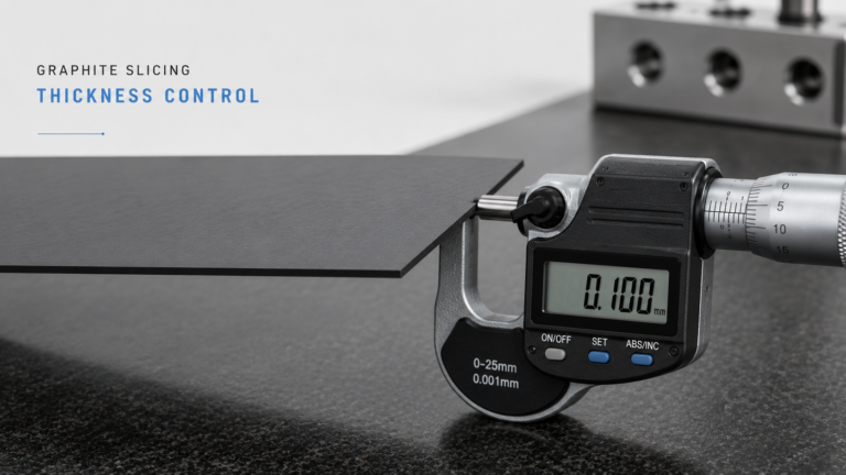
| Dial indicator on surface plate | Flatness + parallelism | 0.001 mm | Production inspection |
| CMM (coordinate measuring machine) | Both + full surface map | 0.001 mm | Incoming inspection, documentation |
| Optical profilometer | Flatness (high detail) | 0,0001 мм | НИОКР, разработка процессов |
Для производственных условий индикатор часового типа на гранитной плите является наиболее практичным сочетанием скорости и точности. Измерьте плоскостность, поместив плиту лицевой стороной вниз на гранитную плиту, проведя индикатором по верхней поверхности и записав общее показание индикатора (TIR). Переверните плиту и повторите для другой стороны. Разница между показаниями TIR дает представление о параллельности.
Связь плоскостности с полной цепочкой качества нарезки
Плоскостность и параллельность графитовых пластин находятся в середине цепочки качества:
- Процесс нарезки параметры определяют начальную геометрию
- Контроль толщины гарантирует, что пластина достигнет целевой толщины — но пластина с хорошим TTV все равно может иметь плохую плоскостность, если проволока была постоянно изогнута
- Дефекты поверхности такие как сколы по краям, могут уменьшить эффективную плоскостность на границе пластины
- Введение напряжений во время нарезки может вызвать коробление после резки, которое нарушает плоскостность после того, как пластина покинет станок
Для полного обзора того, как эти факторы качества взаимосвязаны, см. наше прецизионная нарезка графита руководство по столпам.