EDM graphite electrode cutting is the first — and most consequential — step in electrode manufacturing. The decisions made at the cutting stage determine blank geometry, internal stress state, edge integrity, and surface condition: four properties that every downstream process either works with or works against.
What Is EDM Graphite Electrode Cutting?
EDM graphite electrode cutting is the process of separating electrode blanks from raw graphite stock using precision cutting equipment — typically diamond wire saws — before shaping and finishing. It is not a rough preparation step. The cutting stage establishes the geometric and material baseline from which the finished electrode is produced, and every error it introduces propagates forward into shaping, finishing, and ultimately, EDM discharge performance.
Electrode cutting is not the first manufacturing step. It is the moment that determines whether the entire downstream process succeeds or fails.
The EDM Electrode Manufacturing Flow
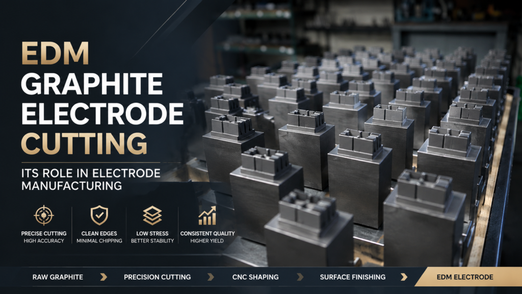
Electrode manufacturing involves three sequential stages: cutting, shaping, and finishing. Each adds precision, but only the first — EDM graphite electrode cutting — establishes the physical foundation that all subsequent work builds on.
| Stage | Verfahren | Primary Goal | Typical Output Tolerance |
|---|---|---|---|
| 1. Cutting | Separate blank from graphite stock | Dimensions, geometry, surface | ±0.1–0.2 mm |
| 2. Shaping | CNC milling, grinding | Detail geometry, form accuracy | ±0.02–0.05 mm |
| 3. Finishing | Surface treatment, cleaning | Surface quality, cleanliness | Ra < 0.8 μm |
The cutting stage outputs a blank: a piece of graphite with the approximate dimensions of the finished electrode, ready for CNC shaping. That blank carries properties — accurate or not, damaged or clean, stressed or relaxed — that the shaping and finishing stages cannot change, only work within.
Wenn das EDM-Graphitelektroden-Schneiden einen Rohling mit korrekten Abmessungen, sauberen Kanten, geringer innerer Spannung und gleichmäßigem Oberflächenzustand liefert, arbeiten Formgebung und Endbearbeitung innerhalb ihrer vorgesehenen Parameter. Wenn das Schneiden Dimensionsfehler, Kantenabsplitterungen, Untergrundrisse oder Restspannungen einführt, verbraucht jede nachfolgende Stufe Kapazität, um Folgen zu absorbieren, anstatt Präzision hinzuzufügen.
Das vollständige Bild, wie das Schneiden in den gesamten Elektroden-Workflow integriert ist, wird im Schneiden von EDM-Graphitelektroden Prozessleitfaden behandelt.
Warum das EDM-Graphitelektroden-Schneiden die Geometriestabilität definiert
Die Toleranzkette funktioniert rückwärts von der Elektrode
Die Elektrodenfertigung basiert auf einer Toleranzkette. Jede Stufe muss eine ausreichend genaue Eingabe erhalten, um ihre Zielausgabe zu produzieren. Diese Kette funktioniert rückwärts von der fertigen Elektrode:
Für eine fertige EDM-Elektrode mit einer Anforderung von ±0,02 mm (Standard für Präzisionsformenbau):
- Die Endbearbeitung verbraucht etwa ±0,005 mm des Budgets
- Die Formgebung (CNC) verbraucht etwa ±0,015 mm
- Das Schneiden muss einen Rohling innerhalb von ±0,08–0,15 mm liefern
Ein Schneidprozess, der ±0,3 mm liefert, hat bereits das Formgebungsbudget aufgebraucht. Die CNC-Stufe arbeitet dann im Fehlerkorrekturmodus – sie entfernt zusätzliches Material, um die Dimensionsreferenz festzulegen, bevor sie mit dem Hinzufügen von Formdetails beginnen kann. Dies verschwendet Zykluszeit, beschleunigt den Werkzeugverschleiß und reduziert das für die fertige Elektrode verfügbare Material.
Die Geometrie wird beim ersten Schnitt festgelegt
Die CNC-Bearbeitung kann Formfehler innerhalb eines begrenzten Bereichs korrigieren. Sie kann kein Material hinzufügen und keine Fehler korrigieren, die den verfügbaren Spielraum überschreiten. Wenn ein Schneidvorgang einen um 0,4 mm zu kleinen Rohling erzeugt, kann die CNC diese Dimension nicht wiederherstellen. Wenn ein Rohling eine Durchbiegung von 0,3 mm über seine Fläche aufweist, muss die Formgebungsstufe Material entfernen, um eine ebene Referenz zu schaffen, bevor sie mit der Bearbeitung der Elektrodengeometrie beginnen kann.
Diamond wire cutting consistently delivers blanks within ±0.05–0.15 mm depending on blank size and graphite grade — keeping downstream stages within their designed operating window.
EDM Graphite Electrode Cutting and Electrode Service Life
Subsurface Damage Depth Determines Wear Consistency
Every cutting process introduces subsurface damage: micro-cracks, grain boundary disruption, and lattice distortion below the visible cut surface. The depth of this damaged layer depends directly on cutting method.
Conventional abrasive sawing (cutoff wheels, band saws) applies high concentrated force at the tool-material interface. On graphite, this force drives subsurface damage 0.3–1.0 mm below the surface — a layer the eye cannot detect but the EDM process will expose.
During electrode service, the EDM discharge erodes the electrode surface progressively. When erosion reaches the subsurface damage layer, electrode behavior changes: wear rate increases, dimensional stability decreases, and discharge consistency degrades. The electrode that appeared identical to its neighbors at the start of a run begins to diverge.
Diamond wire cutting distributes cutting force across the full wire contact length rather than concentrating it at a tool edge. This reduces subsurface damage depth to 0.05–0.1 mm — well below the depth that typical EDM service cycles reach. According to SGL Carbon, the microstructural integrity of EDM graphite electrodes directly affects both wear ratio and mold surface finish quality.
Edge Integrity at Electrode Corners
EDM electrode corners are geometrically critical. Sharp, clean corners define the cavity details that the mold must reproduce. Edge chipping at the cutting stage compromises those details before CNC shaping begins.
Conventional cutting applies concentrated force at the tool exit point. On graphite — a material with low fracture toughness — this produces chips at blank edges ranging from 0.1 to 0.5 mm. These chips are not always visible without magnification. Shaping can remove chipped edges, but only by consuming material allocated for the finished electrode geometry.
Kantintegrität an den Elektrodenkanten EDM-Elektrodenkanten sind geometrisch kritisch. Scharfe, saubere Kanten definieren die Kavitätsdetails, die die Form reproduzieren muss. Kantenspäne in der Schneidstufe beeinträchtigen diese Details, bevor die CNC-Bearbeitung beginnt..
Konventionelles Schneiden übt konzentrierte Kraft am Austrittspunkt des Werkzeugs aus. Bei Graphit – einem Material mit geringer Bruchzähigkeit – entstehen an den Blankkanten Späne mit einer Tiefe von 0,1 bis 0,5 mm. Diese Späne sind ohne Vergrößerung nicht immer sichtbar. Die Formgebung kann beschädigte Kanten entfernen, aber nur durch Verbrauch von Material, das für die fertige Elektrodengeometrie vorgesehen ist.
Residual Stress from Cutting Cannot Be Removed Downstream
Cutting generates both heat and mechanical force at the cut surface. In graphite — with its layered sp² carbon structure — cutting forces acting across the crystal planes create residual stress that redistributes across the blank. This stress does not dissipate during shaping or finishing. It remains locked in the material until the thermal and electrical environment of the EDM process releases it.
Residual stress released during EDM discharge produces micro-fracture events at the electrode surface. These events interrupt discharge stability, create arc conditions, and generate pitting on the mold surface. In precision mold applications, even small discharge instabilities produce surface defects requiring rework.
Reducing residual stress at the EDM graphite electrode cutting stage is the only point in the manufacturing flow where this problem can be addressed. Diamond wire cutting reduces cutting force and heat generation compared to abrasive methods, producing blanks with a lower initial stress state.
Surface Uniformity Controls Discharge Initiation
Beyond stress, the uniformity of the cut surface controls how discharge initiates and propagates across the electrode face during EDM operation.
A surface with consistent micro-topography produces consistent discharge: each pulse initiates at approximately the same stand-off distance and removes approximately the same volume of workpiece material. A surface with variable micro-topography — caused by inconsistent cutting conditions — produces variable discharge. Some pulses initiate early at high spots, some late at low spots. The result is non-uniform material removal, increased arc frequency, and degraded mold surface finish.
The relationship between graphite cutting-induced surface stress and downstream performance is covered in detail in graphite slicing stress and surface effects.
From Raw Graphite Block to Ready-to-Use EDM Electrode
What the Cutting Stage Actually Delivers
A graphite block enters the EDM graphite electrode cutting stage as raw material. It exits as a blank with four defined properties:
Dimensions — the starting point for all tolerance calculations in shaping and finishing. Errors here cannot be corrected, only partially compensated.
Surface condition — determines the shaping allowance needed and the finishing steps required. Surface damage from cutting adds to both.
Internal stress state — locked into the material by the cutting process. No downstream step removes it. It releases during EDM operation.
Edge condition — determines whether corner geometry is recoverable in shaping, or whether chips already exceed the available material allowance.
All four properties are determined in the seconds the cutting wire passes through the graphite block. No subsequent process can add dimension, extract stress, or restore a chipped corner beyond what EDM graphite electrode cutting delivered.
Recognizing When Cutting Is the Root Cause
Electrode manufacturers whose downstream processes show these patterns should investigate cutting as the root cause:
- Inconsistent electrode wear across a production batch — variable cutting conditions produce variable subsurface damage, which produces variable wear behavior in EDM
- Dimensional drift within a production run — cutting process not thermally stable; blank dimensions shift as equipment warms up through a shift
- Shaping scrap rate above 3–5% — blank dimensions or edge condition outside the CNC process window
- EDM surface finish variation between electrodes from the same batch — surface condition and stress state variation from cutting propagates directly to discharge behavior
The comparison between cutting approaches and their effect on downstream consistency is documented in graphite electrode cutting vs machining, including production data on cycle time and scrap rate differences.
For electrode manufacturers looking to evaluate their cutting process as the foundation of electrode quality, contact us to discuss wire specification, machine setup, and process parameter optimization for your graphite grade and electrode geometry requirements.