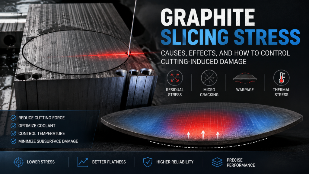
Graphite slicing stress is an unavoidable consequence of mechanical cutting — but it can be managed. Every time a blade or wire passes through a graphite billet, it generates mechanical forces that create residual stress in the finished wafer. Uncontrolled graphite slicing stress causes warping, microcracking, and dimensional instability that can make wafers unusable for precision applications such as EDM electrodes, semiconductor carriers, and fuel cell bipolar plates.
This guide explains where slicing stress comes from, how it affects wafer quality, and what process adjustments reduce stress-related damage in production.
What Causes Graphite Slicing Stress?
Slicing stress in graphite originates from three mechanical interactions during the cutting process:
Cutting Force Distribution
When a diamond wire or blade enters the graphite billet, it applies compressive force ahead of the cutting edge and tensile force behind it. The material directly beneath the cut experiences plastic deformation at the microscale — graphite grains are fractured, displaced, and compressed into a thin subsurface damage layer.
This damaged layer retains residual compressive stress. The deeper the damage zone extends, the more stress is locked into the wafer surface. In fine-grained isostatic graphite (grain size ≤10 μm), the damage zone is typically shallow — 10 to 50 μm — because the uniform microstructure fractures cleanly. Coarser graphite grades develop deeper and more irregular damage zones.
Thermische Effekte
Friction between the cutting element and graphite generates localized heat. Graphite has relatively low thermal conductivity compared to metals, so heat concentrates near the cut surface rather than dissipating quickly through the billet. This localized heating causes differential thermal expansion — the warm surface layer expands while the cooler bulk material constrains it, creating thermal stress.
If coolant delivery is insufficient, surface temperatures can rise high enough to cause thermal shock in the near-surface region. This produces a network of microcracks that weaken the wafer and create stress concentration points. Proper coolant management is essential — OSHA’s graphite processing guidelines also emphasize adequate wet cutting practices for dust and heat control.
Clamping and Fixturing Stress
The billet must be held rigidly during slicing. Excessive clamping pressure, uneven fixture surfaces, or poor adhesive bonding between the billet and mounting block introduces external stress before cutting even begins. This pre-stress combines with cutting-induced stress and can amplify warping in thin wafers.
How Graphite Slicing Stress Affects Wafer Quality
Residual stress from slicing manifests in several measurable quality problems:
Wafer warping (bow). Stress asymmetry between the two faces of a wafer causes it to curve. If the top surface has higher compressive stress than the bottom, the wafer bows upward. For wafers thinner than 1 mm, even small stress imbalances produce visible warping. This directly compromises Ebenheits- und Parallelitätsproblem specifications.
Microcracking. Excessive cutting force or thermal shock creates cracks in the subsurface damage layer. These cracks may not be visible to the naked eye but propagate during downstream processing (lapping, handling) or under thermal cycling in end-use applications. Microcracking is one of the most critical slicing defects because it causes unpredictable part failure.
Dimensional instability. Residual stress can relax over time or when the wafer is heated during subsequent processing. As stress releases, the wafer dimensions change — thickness becomes uneven, edges shift, and previously flat surfaces develop curvature. This is particularly problematic for applications requiring tight Dickenkontrolle.
Reduced mechanical strength. The subsurface damage layer weakens the wafer’s effective cross-section. A 0.5 mm wafer with 50 μm of damage on each face has only 80% of its thickness carrying structural load. For thin graphite substrates, this strength reduction limits handling and assembly options.

Measuring Graphite Slicing Stress
Quantifying residual stress helps identify process problems and verify improvements:
Surface Profilometry
Measuring wafer bow (warp) with a surface profilometer or coordinate measuring machine (CMM) provides an indirect but practical stress indicator. Higher bow values indicate greater stress asymmetry. Track bow measurements across production batches to detect process drift.
Raman Spectroscopy
Raman spectroscopy can measure stress in graphite by detecting shifts in the G-band peak (~1580 cm⁻¹). Compressive stress shifts the peak to higher wavenumbers; tensile stress shifts it lower. This technique provides localized stress mapping across the wafer surface, identifying stress concentration zones.
Layer Removal Method
Progressively removing material from one face of the wafer (by lapping or etching) while measuring curvature change reveals the stress depth profile. As stressed material is removed, the wafer’s curvature changes, allowing calculation of the stress magnitude at each depth. This destructive method is used for process development rather than production monitoring.
How to Reduce Graphite Slicing Stress in Production
Optimize Feed Rate and Cutting Speed
Feed rate has the strongest influence on cutting force — and therefore on slicing stress. Reducing feed rate decreases the force per unit length on the cutting element, which reduces both mechanical damage depth and heat generation.
However, reducing feed rate too much extends cycle time and may cause the wire or blade to dwell in one position, creating localized thermal damage. The optimal feed rate balances:
- Subsurface damage depth (lower feed = shallower damage)
- Thermal input (moderate feed = less dwelling heat)
- Throughput (production speed requirement)
For most isostatic graphite grades, a feed rate reduction of 20–30% from the maximum stable cutting rate typically produces measurable stress reduction without significant throughput penalty.
Use Proper Coolant Strategy
Coolant serves two stress-reduction functions: it removes heat from the cutting zone and flushes away swarf that would increase cutting resistance.
Effective coolant practices for stress control:
- Flow rate: Sufficient to maintain a continuous film across the entire cutting interface — not just the entry point
- Temperature: Coolant temperature should be stable; fluctuations cause variable thermal stress in the workpiece
- Nozzle positioning: Direct coolant at both the wire/blade entry and exit points of the cut
- Filtration: Recirculated coolant must be filtered to remove graphite particles that increase abrasive wear and force
According to SGL Carbon’s machining recommendations for specialty graphites, wet cutting with adequate coolant flow is essential for maintaining surface integrity in fine-grained grades.
Select Appropriate Wire or Blade Parameters
Thinner cutting elements generally produce less stress because they remove less material and apply lower total cutting force. However, thinner wires are more susceptible to deflection, which can create asymmetric stress patterns.
Key parameter relationships:
| Parameter | Effect on Stress | Trade-off |
|---|---|---|
| Wire diameter ↓ | Less material removal force → lower stress | More deflection risk |
| Diamond grit size ↓ | Finer cut surface → shallower damage | Slower cutting speed |
| Wire tension ↑ | Less deflection → more uniform stress | Higher wire breakage risk |
| Wire speed ↑ | Less force per grit → lower local stress | More heat generation |
The goal is not to minimize any single parameter but to find the combination that produces the lowest total stress for your specific graphite grade and wafer geometry. This optimization is a core part of the Präzisionsgraphitschneiden process setup.
Control Billet Mounting and Fixturing
Mounting-related stress is entirely preventable with proper technique:
- Use uniform adhesive layers between billet and mounting block — air gaps or uneven adhesive thickness create stress concentration points
- Match mounting block material to graphite’s thermal expansion characteristics — dissimilar expansion rates create stress during temperature changes
- Apply minimum clamping force — only enough to prevent movement during cutting; excessive force pre-loads the billet with stress
- Allow stress relief time after mounting before starting the cut — adhesive curing can introduce temporary stress
Post-Slicing Stress Relief
For applications requiring the lowest possible residual stress, post-slicing treatments can reduce stress levels:
Annealing. Heating wafers to moderate temperature (typically 200–400°C for graphite, depending on grade and binder content) in an inert atmosphere allows residual stress to relax through microstructural rearrangement. Cool slowly to avoid introducing new thermal stress.
Lapping both faces. Removing equal amounts of material from both wafer faces eliminates the asymmetric damage layer that causes bow. Even a light lapping pass (removing 20–50 μm per face) significantly reduces stress-induced warping. This also addresses kerf loss considerations — the total material removed in lapping should be factored into your slicing plan.
Graphite Slicing Stress Control Across Different Graphite Grades
Not all graphite responds equally to cutting stress. The graphite grade determines both the magnitude of slicing stress and the appropriate mitigation strategy:
Isostatic graphite (grain size ≤10 μm): Fine, uniform microstructure produces shallow, consistent damage zones. These grades tolerate aggressive cutting parameters better than coarse grades. Stress control is primarily about thermal management and wire tension.
Extruded graphite (grain size 0.5–2 mm): Anisotropic structure means stress behavior varies with cutting direction. Cutting perpendicular to the extrusion direction typically produces higher stress. Slower feed rates and careful orientation planning reduce stress-related problems.
Molded graphite (grain size 0.1–0.5 mm): Moderate grain size with more isotropic properties than extruded grades. Stress levels fall between isostatic and extruded. Standard optimization of feed rate and coolant usually provides adequate stress control.
Das Verständnis des Verhaltens Ihrer spezifischen Graphitgüte ist unerlässlich für die Festlegung geeigneter Schneidparameter in Ihrem slicing process.