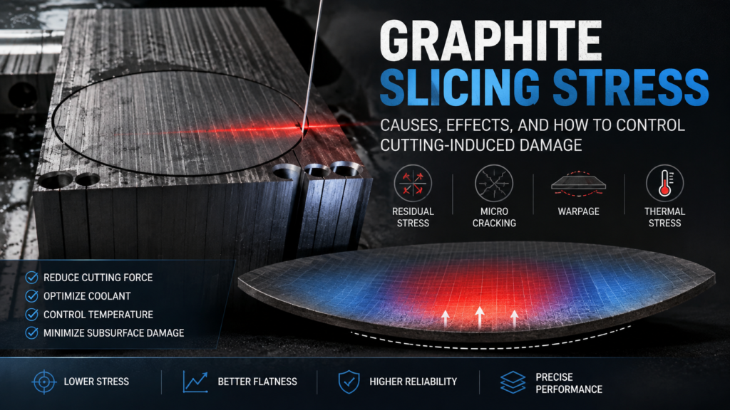
Graphite slicing stress is an unavoidable consequence of mechanical cutting — but it can be managed. Every time a blade or wire passes through a graphite billet, it generates mechanical forces that create residual stress in the finished wafer. Uncontrolled graphite slicing stress causes warping, microcracking, and dimensional instability that can make wafers unusable for precision applications such as EDM electrodes, semiconductor carriers, and fuel cell bipolar plates.
This guide explains where slicing stress comes from, how it affects wafer quality, and what process adjustments reduce stress-related damage in production.
What Causes Graphite Slicing Stress?
Slicing stress in graphite originates from three mechanical interactions during the cutting process:
Cutting Force Distribution
When a diamond wire or blade enters the graphite billet, it applies compressive force ahead of the cutting edge and tensile force behind it. The material directly beneath the cut experiences plastic deformation at the microscale — graphite grains are fractured, displaced, and compressed into a thin subsurface damage layer.
This damaged layer retains residual compressive stress. The deeper the damage zone extends, the more stress is locked into the wafer surface. In fine-grained isostatic graphite (grain size ≤10 μm), the damage zone is typically shallow — 10 to 50 μm — because the uniform microstructure fractures cleanly. Coarser graphite grades develop deeper and more irregular damage zones.
열 효과
Friction between the cutting element and graphite generates localized heat. Graphite has relatively low thermal conductivity compared to metals, so heat concentrates near the cut surface rather than dissipating quickly through the billet. This localized heating causes differential thermal expansion — the warm surface layer expands while the cooler bulk material constrains it, creating thermal stress.
If coolant delivery is insufficient, surface temperatures can rise high enough to cause thermal shock in the near-surface region. This produces a network of microcracks that weaken the wafer and create stress concentration points. Proper coolant management is essential — OSHA’s graphite processing guidelines also emphasize adequate wet cutting practices for dust and heat control.
Clamping and Fixturing Stress
The billet must be held rigidly during slicing. Excessive clamping pressure, uneven fixture surfaces, or poor adhesive bonding between the billet and mounting block introduces external stress before cutting even begins. This pre-stress combines with cutting-induced stress and can amplify warping in thin wafers.
How Graphite Slicing Stress Affects Wafer Quality
Residual stress from slicing manifests in several measurable quality problems:
Wafer warping (bow). Stress asymmetry between the two faces of a wafer causes it to curve. If the top surface has higher compressive stress than the bottom, the wafer bows upward. For wafers thinner than 1 mm, even small stress imbalances produce visible warping. This directly compromises flatness and parallelism specifications.
Microcracking. Excessive cutting force or thermal shock creates cracks in the subsurface damage layer. These cracks may not be visible to the naked eye but propagate during downstream processing (lapping, handling) or under thermal cycling in end-use applications. Microcracking is one of the most critical slicing defects because it causes unpredictable part failure.
Dimensional instability. Residual stress can relax over time or when the wafer is heated during subsequent processing. As stress releases, the wafer dimensions change — thickness becomes uneven, edges shift, and previously flat surfaces develop curvature. This is particularly problematic for applications requiring tight thickness control.
Reduced mechanical strength. The subsurface damage layer weakens the wafer’s effective cross-section. A 0.5 mm wafer with 50 μm of damage on each face has only 80% of its thickness carrying structural load. For thin graphite substrates, this strength reduction limits handling and assembly options.

Measuring Graphite Slicing Stress
Quantifying residual stress helps identify process problems and verify improvements:
Surface Profilometry
Measuring wafer bow (warp) with a surface profilometer or coordinate measuring machine (CMM) provides an indirect but practical stress indicator. Higher bow values indicate greater stress asymmetry. Track bow measurements across production batches to detect process drift.
Raman Spectroscopy
Raman spectroscopy can measure stress in graphite by detecting shifts in the G-band peak (~1580 cm⁻¹). Compressive stress shifts the peak to higher wavenumbers; tensile stress shifts it lower. This technique provides localized stress mapping across the wafer surface, identifying stress concentration zones.
Layer Removal Method
Progressively removing material from one face of the wafer (by lapping or etching) while measuring curvature change reveals the stress depth profile. As stressed material is removed, the wafer’s curvature changes, allowing calculation of the stress magnitude at each depth. This destructive method is used for process development rather than production monitoring.
How to Reduce Graphite Slicing Stress in Production
Optimize Feed Rate and Cutting Speed
Feed rate has the strongest influence on cutting force — and therefore on slicing stress. Reducing feed rate decreases the force per unit length on the cutting element, which reduces both mechanical damage depth and heat generation.
However, reducing feed rate too much extends cycle time and may cause the wire or blade to dwell in one position, creating localized thermal damage. The optimal feed rate balances:
- Subsurface damage depth (lower feed = shallower damage)
- Thermal input (moderate feed = less dwelling heat)
- Throughput (production speed requirement)
For most isostatic graphite grades, a feed rate reduction of 20–30% from the maximum stable cutting rate typically produces measurable stress reduction without significant throughput penalty.
Use Proper Coolant Strategy
Coolant serves two stress-reduction functions: it removes heat from the cutting zone and flushes away swarf that would increase cutting resistance.
Effective coolant practices for stress control:
- Flow rate: Sufficient to maintain a continuous film across the entire cutting interface — not just the entry point
- Temperature: Coolant temperature should be stable; fluctuations cause variable thermal stress in the workpiece
- 노즐 위치 지정: 절단부의 와이어/블레이드 진입 및 진출 지점에 모두 냉각수를 직접 분사하십시오.
- 여과: 재순환 냉각수는 흑연 입자를 제거하기 위해 여과해야 합니다. 이 입자는 연마 마모를 증가시키고 힘을 가합니다.
에 따르면 SGL Carbon의 특수 흑연 가공 권장 사항, 습식 절단 시 적절한 냉각수 흐름은 미세 입자 등급의 표면 무결성을 유지하는 데 필수적입니다.
적절한 와이어 또는 블레이드 매개변수 선택
더 얇은 절단 요소는 재료 제거량이 적고 총 절단력이 낮기 때문에 일반적으로 응력이 덜 발생합니다. 그러나 더 얇은 와이어는 편향에 더 취약하여 비대칭 응력 패턴을 생성할 수 있습니다.
주요 매개변수 관계:
| 매개변수 | 응력에 미치는 영향 | Trade-off |
|---|---|---|
| 와이어 직경 ↓ | 재료 제거력 감소 → 응력 감소 | 편향 위험 증가 |
| 다이아몬드 입자 크기 ↓ | 더 고운 절단 표면 → 더 얕은 손상 | 더 느린 절단 속도 |
| 와이어 장력 ↑ | 편향 감소 → 더 균일한 응력 | 와이어 파손 위험 증가 |
| 와이어 속도 ↑ | 입자당 힘 감소 → 국소 응력 감소 | 더 많은 열 발생 |
목표는 단일 매개변수를 최소화하는 것이 아니라 특정 흑연 등급 및 웨이퍼 형상에 대해 가장 낮은 총 응력을 생성하는 조합을 찾는 것입니다. 이 최적화는 핵심 부분입니다. 정밀 흑연 슬라이싱 공정 설정.
빌렛 장착 및 고정 장치 제어
올바른 기술로 장착 관련 응력을 완전히 방지할 수 있습니다.
- 균일한 접착제 층 사용 빌렛과 장착 블록 사이 — 공극 또는 고르지 않은 접착제 두께는 응력 집중 지점을 생성합니다.
- 장착 블록 재료 일치 흑연의 열팽창 특성 — 다른 팽창률은 온도 변화 중에 응력을 생성합니다.
- 최소 클램핑력 적용 — 절단 중 움직임을 방지할 만큼만; 과도한 힘은 빌렛에 미리 응력을 가합니다.
- 응력 완화 시간 허용 장착 후 절단 시작 전 — 접착제 경화는 일시적인 응력을 유발할 수 있습니다.
절단 후 응력 완화
가능한 가장 낮은 잔류 응력이 필요한 응용 분야의 경우 절단 후 처리를 통해 응력 수준을 줄일 수 있습니다.
어닐링. 웨이퍼를 불활성 분위기에서 적당한 온도(흑연의 경우 일반적으로 200–400°C, 등급 및 바인더 함량에 따라 다름)로 가열하면 미세 구조 재배열을 통해 잔류 응력이 완화됩니다. 새로운 열 응력을 유발하지 않도록 천천히 냉각하십시오.
양면 래핑. 웨이퍼 양면에서 동일한 양의 재료를 제거하면 휨을 유발하는 비대칭 손상층이 제거됩니다. 가벼운 래핑 패스(면당 20–50 μm 제거)도 응력 유발 휨을 크게 줄입니다. 이것은 또한 다룹니다. kerf loss 고려 사항 — 래핑에서 제거된 총 재료는 절단 계획에 고려되어야 합니다.
다른 흑연 등급에 걸친 흑연 절단 응력 제어
모든 흑연이 절단 응력에 동일하게 반응하는 것은 아닙니다. 흑연 등급은 절단 응력의 크기와 적절한 완화 전략을 모두 결정합니다.
등방성 흑연(입자 크기 ≤10 μm): 미세하고 균일한 미세 구조는 얕고 일관된 손상 영역을 생성합니다. 이러한 등급은 조밀한 등급보다 공격적인 절단 매개변수를 더 잘 견딥니다. 응력 제어는 주로 열 관리 및 와이어 장력에 관한 것입니다.
압출 흑연(입자 크기 0.5–2 mm): 비등방성 구조는 절단 방향에 따라 응력 거동이 달라짐을 의미합니다. 압출 방향에 수직으로 절단하면 일반적으로 더 높은 응력이 발생합니다. 더 느린 공급 속도와 신중한 방향 계획은 응력 관련 문제를 줄입니다.
성형 흑연(입자 크기 0.1–0.5 mm): 압출 등급보다 더 등방성 특성을 가진 중간 입자 크기. 응력 수준은 등방성과 압출 사이입니다. 공급 속도 및 냉각수의 표준 최적화는 일반적으로 적절한 응력 제어를 제공합니다.
특정 흑연 등급의 거동을 이해하는 것은 적절한 슬라이싱 매개변수를 설정하는 데 필수적입니다. slicing process.