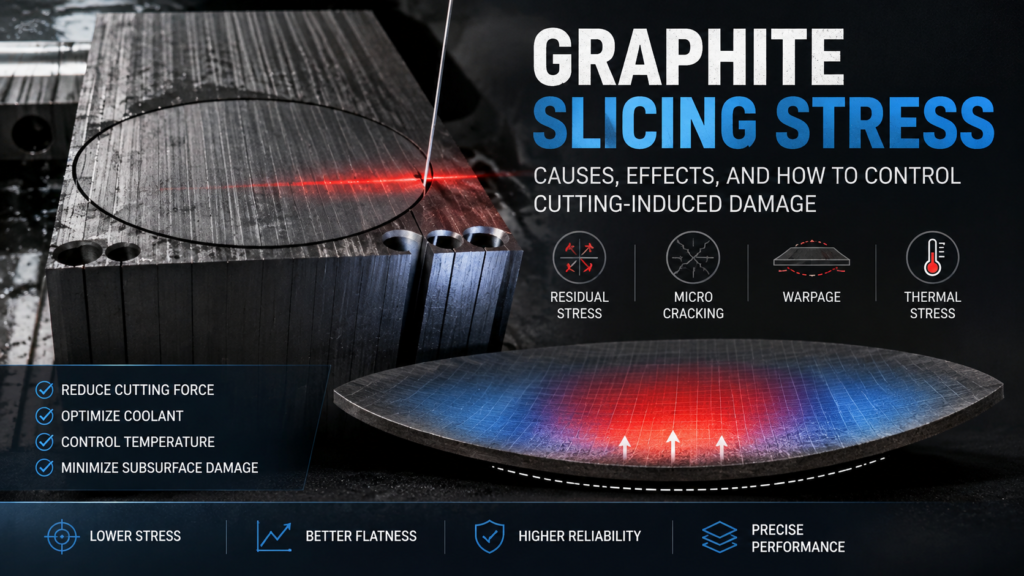
Graphite slicing stress is an unavoidable consequence of mechanical cutting — but it can be managed. Every time a blade or wire passes through a graphite billet, it generates mechanical forces that create residual stress in the finished wafer. Uncontrolled graphite slicing stress causes warping, microcracking, and dimensional instability that can make wafers unusable for precision applications such as EDM electrodes, semiconductor carriers, and fuel cell bipolar plates.
This guide explains where slicing stress comes from, how it affects wafer quality, and what process adjustments reduce stress-related damage in production.
What Causes Graphite Slicing Stress?
Slicing stress in graphite originates from three mechanical interactions during the cutting process:
Cutting Force Distribution
When a diamond wire or blade enters the graphite billet, it applies compressive force ahead of the cutting edge and tensile force behind it. The material directly beneath the cut experiences plastic deformation at the microscale — graphite grains are fractured, displaced, and compressed into a thin subsurface damage layer.
This damaged layer retains residual compressive stress. The deeper the damage zone extends, the more stress is locked into the wafer surface. In fine-grained isostatic graphite (grain size ≤10 μm), the damage zone is typically shallow — 10 to 50 μm — because the uniform microstructure fractures cleanly. Coarser graphite grades develop deeper and more irregular damage zones.
Thermal Effects
Friction between the cutting element and graphite generates localized heat. Graphite has relatively low thermal conductivity compared to metals, so heat concentrates near the cut surface rather than dissipating quickly through the billet. This localized heating causes differential thermal expansion — the warm surface layer expands while the cooler bulk material constrains it, creating thermal stress.
If coolant delivery is insufficient, surface temperatures can rise high enough to cause thermal shock in the near-surface region. This produces a network of microcracks that weaken the wafer and create stress concentration points. Proper coolant management is essential — Các hướng dẫn xử lý graphite của OSHA also emphasize adequate wet cutting practices for dust and heat control.
Clamping and Fixturing Stress
The billet must be held rigidly during slicing. Excessive clamping pressure, uneven fixture surfaces, or poor adhesive bonding between the billet and mounting block introduces external stress before cutting even begins. This pre-stress combines with cutting-induced stress and can amplify warping in thin wafers.
How Graphite Slicing Stress Affects Wafer Quality
Residual stress from slicing manifests in several measurable quality problems:
Wafer warping (bow). Stress asymmetry between the two faces of a wafer causes it to curve. If the top surface has higher compressive stress than the bottom, the wafer bows upward. For wafers thinner than 1 mm, even small stress imbalances produce visible warping. This directly compromises flatness and parallelism specifications.
Microcracking. Excessive cutting force or thermal shock creates cracks in the subsurface damage layer. These cracks may not be visible to the naked eye but propagate during downstream processing (lapping, handling) or under thermal cycling in end-use applications. Microcracking is one of the most critical các khuyết tật cắt lát because it causes unpredictable part failure.
Dimensional instability. Residual stress can relax over time or when the wafer is heated during subsequent processing. As stress releases, the wafer dimensions change — thickness becomes uneven, edges shift, and previously flat surfaces develop curvature. This is particularly problematic for applications requiring tight thickness control.
Reduced mechanical strength. The subsurface damage layer weakens the wafer’s effective cross-section. A 0.5 mm wafer with 50 μm of damage on each face has only 80% of its thickness carrying structural load. For thin graphite substrates, this strength reduction limits handling and assembly options.

Measuring Graphite Slicing Stress
Quantifying residual stress helps identify process problems and verify improvements:
Surface Profilometry
Measuring wafer bow (warp) with a surface profilometer or coordinate measuring machine (CMM) provides an indirect but practical stress indicator. Higher bow values indicate greater stress asymmetry. Track bow measurements across production batches to detect process drift.
Raman Spectroscopy
Raman spectroscopy can measure stress in graphite by detecting shifts in the G-band peak (~1580 cm⁻¹). Compressive stress shifts the peak to higher wavenumbers; tensile stress shifts it lower. This technique provides localized stress mapping across the wafer surface, identifying stress concentration zones.
Layer Removal Method
Progressively removing material from one face of the wafer (by lapping or etching) while measuring curvature change reveals the stress depth profile. As stressed material is removed, the wafer’s curvature changes, allowing calculation of the stress magnitude at each depth. This destructive method is used for process development rather than production monitoring.
How to Reduce Graphite Slicing Stress in Production
Optimize Feed Rate and Cutting Speed
Feed rate has the strongest influence on cutting force — and therefore on slicing stress. Reducing feed rate decreases the force per unit length on the cutting element, which reduces both mechanical damage depth and heat generation.
However, reducing feed rate too much extends cycle time and may cause the wire or blade to dwell in one position, creating localized thermal damage. The optimal feed rate balances:
- Subsurface damage depth (lower feed = shallower damage)
- Thermal input (moderate feed = less dwelling heat)
- Throughput (production speed requirement)
For most isostatic graphite grades, a feed rate reduction of 20–30% from the maximum stable cutting rate typically produces measurable stress reduction without significant throughput penalty.
Use Proper Coolant Strategy
Coolant serves two stress-reduction functions: it removes heat from the cutting zone and flushes away swarf that would increase cutting resistance.
Effective coolant practices for stress control:
- Flow rate: Sufficient to maintain a continuous film across the entire cutting interface — not just the entry point
- Temperature: Nhiệt độ chất làm mát phải ổn định; sự dao động gây ra ứng suất nhiệt thay đổi trong phôi
- Định vị vòi phun: Hướng chất làm mát vào cả điểm vào và điểm ra của dây/lưỡi cắt
- Lọc: Chất làm mát tuần hoàn phải được lọc để loại bỏ các hạt than chì làm tăng mài mòn do ma sát và lực
Theo các khuyến nghị gia công của SGL Carbon đối với than chì đặc biệt, cắt ướt với lưu lượng chất làm mát đầy đủ là điều cần thiết để duy trì tính toàn vẹn bề mặt ở các loại hạt mịn.
Chọn Thông số Dây hoặc Lưỡi cắt Phù hợp
Các bộ phận cắt mỏng hơn thường tạo ra ít ứng suất hơn vì chúng loại bỏ ít vật liệu hơn và tạo ra lực cắt tổng thể thấp hơn. Tuy nhiên, dây mỏng hơn dễ bị lệch hơn, điều này có thể tạo ra các mẫu ứng suất không đối xứng.
Các mối quan hệ thông số chính:
| Tham số | Ảnh hưởng đến Ứng suất | Trade-off |
|---|---|---|
| Đường kính dây ↓ | Lực loại bỏ vật liệu ít hơn → ứng suất thấp hơn | Rủi ro lệch nhiều hơn |
| Kích thước hạt kim cương ↓ | Bề mặt cắt mịn hơn → hư hỏng nông hơn | Tốc độ cắt chậm hơn |
| Độ căng dây ↑ | Ít lệch hơn → ứng suất đồng đều hơn | Rủi ro đứt dây cao hơn |
| Tốc độ dây ↑ | Lực trên mỗi hạt ít hơn → ứng suất cục bộ thấp hơn | Tạo ra nhiều nhiệt hơn |
Mục tiêu không phải là giảm thiểu bất kỳ thông số đơn lẻ nào mà là tìm ra sự kết hợp tạo ra tổng ứng suất thấp nhất cho loại than chì và hình dạng tấm wafer cụ thể của bạn. Việc tối ưu hóa này là một phần cốt lõi của cắt lát than chì chính xác thiết lập quy trình.
Kiểm soát Việc Gắn và Cố định Phôi
Ứng suất liên quan đến việc gắn kết hoàn toàn có thể tránh được với kỹ thuật phù hợp:
- Sử dụng các lớp keo dán đồng nhất giữa phôi và khối gắn — các khoảng hở không khí hoặc độ dày keo không đều tạo ra các điểm tập trung ứng suất
- Khớp vật liệu khối gắn với đặc tính giãn nở nhiệt của than chì — tốc độ giãn nở khác nhau tạo ra ứng suất trong quá trình thay đổi nhiệt độ
- Áp dụng lực kẹp tối thiểu — chỉ đủ để ngăn chuyển động trong quá trình cắt; lực quá mức làm biến dạng phôi với ứng suất
- Cho phép thời gian giảm ứng suất sau khi gắn trước khi bắt đầu cắt — quá trình đóng rắn keo có thể gây ra ứng suất tạm thời
Giảm ứng suất sau khi cắt lát
Đối với các ứng dụng yêu cầu ứng suất dư thấp nhất có thể, các phương pháp xử lý sau khi cắt lát có thể giảm mức ứng suất:
Ủ nhiệt. Gia nhiệt các tấm wafer đến nhiệt độ vừa phải (thường là 200–400°C đối với than chì, tùy thuộc vào loại và hàm lượng chất kết dính) trong môi trường trơ cho phép ứng suất dư giảm thông qua sắp xếp lại vi cấu trúc. Làm nguội chậm để tránh tạo ra ứng suất nhiệt mới.
Mài cả hai mặt. Loại bỏ lượng vật liệu bằng nhau khỏi cả hai mặt của tấm wafer sẽ loại bỏ lớp hư hỏng không đối xứng gây ra cong vênh. Ngay cả một lần mài nhẹ (loại bỏ 20–50 μm mỗi mặt) cũng làm giảm đáng kể độ cong vênh do ứng suất. Điều này cũng giải quyết kerf loss các cân nhắc — tổng lượng vật liệu được loại bỏ trong quá trình mài phải được tính vào kế hoạch cắt lát của bạn.
Kiểm soát Ứng suất Cắt Than chì trên Các Loại Than chì Khác nhau
Không phải tất cả than chì đều phản ứng như nhau với ứng suất cắt. Loại than chì xác định cả độ lớn của ứng suất cắt và chiến lược giảm thiểu phù hợp:
Than chì đẳng hướng (kích thước hạt ≤10 μm): Vi cấu trúc mịn, đồng nhất tạo ra các vùng hư hỏng nông, nhất quán. Các loại này chịu được các thông số cắt khắc nghiệt tốt hơn các loại hạt thô. Kiểm soát ứng suất chủ yếu liên quan đến quản lý nhiệt và độ căng dây.
Than chì ép đùn (kích thước hạt 0,5–2 mm): Cấu trúc dị hướng có nghĩa là hành vi ứng suất thay đổi theo hướng cắt. Cắt vuông góc với hướng ép đùn thường tạo ra ứng suất cao hơn. Tốc độ nạp chậm hơn và lập kế hoạch định hướng cẩn thận làm giảm các vấn đề liên quan đến ứng suất.
Than chì đúc (kích thước hạt 0,1–0,5 mm): Moderate grain size with more isotropic properties than extruded grades. Stress levels fall between isostatic and extruded. Standard optimization of feed rate and coolant usually provides adequate stress control.
Understanding your specific graphite grade’s behavior is essential for setting appropriate slicing parameters in your slicing process.