Tổn thất rãnh cắt lát graphite là vật liệu bị phá hủy bởi bộ phận cắt trong mỗi lần đi qua một khối graphite. Nó trở thành phoi — không phải sản phẩm. Trong các hoạt động cắt lát chính xác, tổn thất rãnh cắt lát graphite có thể tiêu tốn 30–50% khối ban đầu tùy thuộc vào loại lưỡi cắt và các thông số quy trình, làm cho nó trở thành nguồn lãng phí vật liệu lớn nhất trong sản xuất lát graphite.
Tổn thất rãnh cắt lát graphite là gì?
Tổn thất rãnh cắt lát graphite là độ dày của vật liệu bị lưỡi cắt hoặc dây cắt loại bỏ trong mỗi lần cắt, nhân với tất cả các lần cắt trong một hoạt động cắt lát. Đó là khoảng trống còn lại sau khi bộ phận cắt đi qua khối — vật liệu bị mài thành các hạt carbon mịn và được rửa trôi dưới dạng phoi thay vì trở thành các lát hoàn chỉnh.
Ba yếu tố xác định độ lớn của tổn thất rãnh cắt:
- Độ dày lưỡi cắt hoặc dây cắt — yếu tố chính. Bộ phận cắt dày hơn sẽ loại bỏ nhiều vật liệu hơn cho mỗi lần cắt.
- Độ lệch và rung động của lưỡi cắt — khi bộ phận cắt bị lệch, rãnh cắt thực tế sẽ vượt quá độ dày vật lý của lưỡi cắt. Các yếu tố này cũng gây ra các khuyết tật cắt lát như sứt mẻ và gợn sóng.
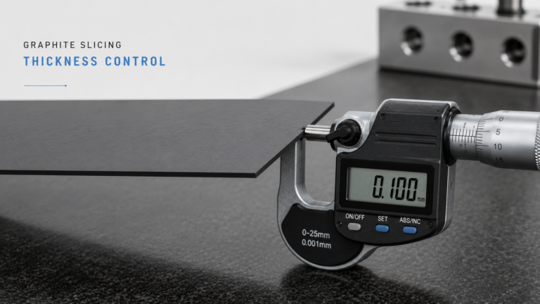
- Khoảng an toàn cho mỗi lát cắt — các nhà khai thác bổ sung thêm phụ cấp để bù đắp cho sự thay đổi độ dày. Kiểm soát độ dày chặt chẽ hơn có nghĩa là biên nhỏ hơn và ít lãng phí hơn.

Tổn thất rãnh cắt lát graphite — Các thông số chính theo phương pháp cắt
| Phương pháp cắt | Chiều rộng rãnh cắt điển hình | Tấm wafer trên mỗi phôi 100 mm (mục tiêu 1 mm) | Tỷ lệ hao hụt do rãnh cắt | Tốt nhất cho |
|---|---|---|---|---|
| Cưa dây kim cương | 0,15–0,35 mm | ~80 (ở rãnh cắt 0,25 mm) | ~20% | Sản xuất tấm wafer chính xác |
| Máy cưa đường kính trong (ID) | 0,3–0,8 mm | ~56–62 | ~35–45% | Cắt tấm wafer đơn chính xác |
| Máy cưa đai | 0,8–1,5 mm | Không áp dụng | >50% | Chỉ cắt khối thô |
| Máy cưa đa dây | 0,15–0,30 mm | ~80+ (đồng thời) | ~18–22% | Sản xuất wafer khối lượng lớn |
Lựa chọn phương pháp cắt có ảnh hưởng lớn hơn đến việc sử dụng vật liệu so với bất kỳ điều chỉnh thông số đơn lẻ nào. Chuyển từ máy cưa ID sang dây kim cương thường cải thiện năng suất wafer trên mỗi phôi lên 20–30%.
Cách giảm thiểu tổn thất rãnh cắt khi cắt lát than chì: Từng bước
Bước 1: Chọn đường kính dây khả thi mỏng nhất
Chuyển từ dây kim cương 0,30 mm sang 0,20 mm làm giảm chiều rộng rãnh cắt khoảng một phần ba. Theo tài liệu kỹ thuật của SGL Carbon về than chì đặc biệt, các loại than chì đẳng áp (kích thước hạt ≤10 μm) rất phù hợp để cắt lát bằng dây mỏng vì cấu trúc vi mô mịn, đồng nhất của chúng làm giảm sứt mẻ cạnh ở các rãnh cắt hẹp.
Trước khi chuyển sang dây mỏng hơn, hãy xác minh:
- Loại than chì của bạn hỗ trợ nó (ưu tiên hạt mịn ≤ 20 μm)
- Hệ thống căng dây có thể duy trì sự ổn định ở đường kính mỏng hơn
- Tuổi thọ dây chấp nhận được ở đường kính giảm
Bước 2: Tối ưu hóa độ căng dây và tốc độ cấp liệu
Độ căng dây không đủ gây ra hiện tượng dây bị lệch, làm tăng chiều rộng rãnh cắt hiệu quả vượt quá đường kính vật lý của dây. Độ căng quá mức sẽ đẩy nhanh hao mòn và đứt gãy.
Tốc độ cấp liệu ảnh hưởng trực tiếp đến độ lệch:
- Quá nhanh → dây bị lệch → rãnh cắt rộng ra → lãng phí vật liệu nhiều hơn
- Quá chậm → nhiệt tích tụ → hư hỏng nhiệt bề mặt cắt
- Tối ưu: tốc độ cấp liệu ổn định duy trì đường cắt thẳng
Giảm tốc độ cấp liệu 20–30% so với tốc độ cắt ổn định tối đa thường giữ cho rãnh cắt thực tế trong phạm vi 0,02–0,05 mm so với đường kính dây. Điều này cũng cải thiện flatness and parallelism tính nhất quán.
Bước 3: Cải thiện việc loại bỏ dung dịch làm mát và phoi vụn
Quá trình cắt graphite tạo ra các hạt carbon mịn làm tắc nghẽn vùng cắt. Sự tích tụ phoi vụn làm tăng lực cản cắt, khiến dây bị lệch và làm rộng rãnh cắt.
Thực hành dung dịch làm mát hiệu quả:
- Tốc độ dòng chảy đủ để liên tục cuốn phoi vụn ra khỏi vùng cắt
- Vòi phun hướng vào cả điểm vào và điểm ra của dây
- Lọc dung dịch làm mát để loại bỏ các hạt mài mòn tái tuần hoàn
- Nhiệt độ dung dịch làm mát ổn định để tránh ứng suất nhiệt thay đổi
Các hướng dẫn xử lý graphite của OSHA cũng nhấn mạnh việc cắt ướt để kiểm soát bụi trong không khí — hệ thống dung dịch làm mát phù hợp phục vụ hai mục đích bằng cách quản lý cả tổn thất rãnh cắt và an toàn nơi làm việc.
Step 4: Maintain Equipment Precision
Worn guide rollers, bearing play, and spindle runout contribute to wire wander. Schedule regular maintenance:
- Guide roller groove inspection and replacement
- Wire tension calibration verification
- Spindle runout measurement (for ID saws)
- Billet mounting fixture alignment check
Step 5: Optimize Billet Dimensions and Orientation
Cut along the longer dimension to maximize wafers per billet and reduce the proportion lost to end trims. If your slicing process allows flexibility in billet orientation, test whether rotating the workpiece reduces total waste.
Graphite Slicing Kerf Loss Troubleshooting
Kerf Width Exceeding Wire Diameter by > 0.1 mm — What to Do?
Check wire tension first — this is the most common cause. Measure actual tension against the manufacturer’s specification for your wire diameter and billet width. If tension is correct, inspect guide rollers for groove wear. Worn rollers allow lateral wire movement that widens the cut. Replace rollers if groove depth exceeds the manufacturer’s tolerance.
Kerf Width Increasing Progressively Through a Production Run?
Wire wear is the primary cause. As diamond grit wears down, cutting efficiency drops and the operator or machine compensates with higher feed force, increasing deflection. Track kerf width against wire usage meters. Establish a wire replacement threshold — typically when kerf width exceeds nominal by more than 0.05 mm — to prevent yield losses in later cuts.
Inconsistent Kerf Width Between First and Last Wafers in a Multi-Wire Cut?
Wire tension distribution across the wire web is uneven. The outermost wires typically have different tension than center wires due to roller geometry and wire path length differences. Calibrate tension across all wire positions and verify roller parallelism. Also check coolant distribution — outer positions may receive less coolant flow, causing localized thermal deflection.
Excessive Edge Chipping Alongside Wide Kerf?
The graphite grain size may be too coarse for the selected wire diameter. Coarse-grained graphite (grain size > 50 μm) tends to fracture in chunks rather than cutting cleanly, producing both wider kerf and chipped edges. Consider switching to a wire with coarser diamond grit or reducing feed rate to allow more controlled material removal.
Graphite Slicing Kerf Loss vs Material Removal in Post-Processing: Where Does More Material Go?
| Loss Source | Typical Amount per Wafer | Controllable? | Impact on Total Yield |
|---|---|---|---|
| Kerf loss (slicing) | 0.15–0.80 mm per cut | Yes — wire/blade selection | Largest single loss |
| Lapping/grinding | 0.02–0.10 mm per face | Partially — depends on slicing quality | Vừa phải |
| End trims (billet) | 2–5 mm total per billet | Partially — billet sizing | Small per wafer |
| Breakage/scrap | Biến | Yes — handling procedures | Biến |
The key insight: reducing kerf loss also reduces downstream lapping requirements. A narrower, more consistent kerf produces wafers with less subsurface damage and better as-cut surface quality, meaning less material must be removed in the lapping or grinding stage. This compounds the yield benefit — every 0.1 mm of kerf reduction saves material twice: once at the saw and again at the lapper.
Kiểm soát ứng suất cắt trong quá trình cắt giúp giảm thêm nhu cầu xử lý sau. Lực cắt thấp hơn có nghĩa là hư hỏng dưới bề mặt nông hơn, có nghĩa là các bước đánh bóng nhẹ hơn và thu được nhiều sản phẩm cuối cùng hơn từ cùng một phôi.

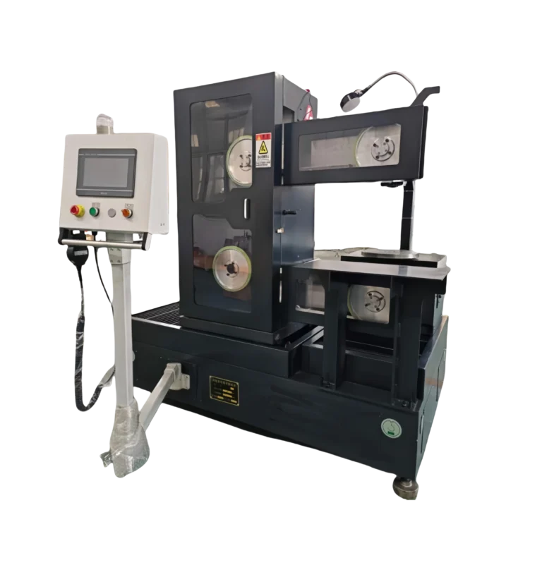
How Diamond Wire Slicing Solves the Kerf Loss Problem
From an engineering perspective, diamond wire technology addresses graphite slicing kerf loss at its root cause — the cutting element thickness.
A modern diamond wire saw configured for graphite operates with 0.20–0.25 mm wire, producing kerf widths 50–70% narrower than ID saw blades. In multi-wire configuration, a single machine cuts hundreds of wafers simultaneously from one billet, with each cut maintaining the same narrow kerf.
Practical results we see in graphite slicing applications:
- Kerf loss ratio reduction from 40–50% (ID saw) to 18–22% (multi-wire diamond)
- Wafer yield increase of 25–35% per billet without changing raw material specifications
- Surface quality improvement that reduces downstream lapping by 30–50%
The critical success factor is matching wire parameters (diameter, grit size, tension) to your specific graphite grade. Fine-grained isostatic graphite tolerates the thinnest wire and produces the narrowest kerf. Coarser extruded grades may require slightly thicker wire but still achieve significant improvement over blade-based cutting.
For a complete overview of how kerf loss fits into your overall slicing strategy, see our cắt lát than chì chính xác guide.