Graphite slicing kerf loss is the material destroyed by the cutting element during every pass through a graphite billet. It becomes swarf — not product. In precision slicing operations, graphite slicing kerf loss can consume 30–50% of the original billet depending on blade type and process parameters, making it the single largest source of material waste in graphite wafer production.
What Is Graphite Slicing Kerf Loss?
Graphite slicing kerf loss is the width of material removed by a blade or wire during each cut, multiplied across all cuts in a slicing operation. It is the gap left behind after the cutting element passes through the billet — material that is ground into fine carbon particles and flushed away as swarf rather than becoming finished wafers.
Three factors determine kerf loss magnitude:
- Blade or wire thickness — the primary driver. A thicker cutting element removes more material per cut.
- Blade deflection and vibration — when the cutting element wanders, actual kerf exceeds the blade’s physical thickness. These same factors cause slicing defects such as chipping and waviness.
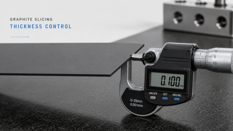
- Safety margin per slice — operators add extra allowance to compensate for thickness variation. Tighter thickness control means smaller margins and less waste.

Graphite Slicing Kerf Loss — Key Parameters by Cutting Method
| Méthode de coupe | Typical Kerf Width | Wafers per 100 mm Billet (1 mm target) | Kerf Loss Ratio | Meilleur pour |
|---|---|---|---|---|
| Scie à fil diamanté | 0.15–0.35 mm | ~80 (at 0.25 mm kerf) | ~20% | Precision wafer production |
| ID (inner diameter) saw | 0.3–0.8 mm | ~56–62 | ~35–45% | Single-wafer precision cuts |
| Band saw | 0.8–1.5 mm | N/A | >50% | Rough block sectioning only |
| Multi-wire saw | 0.15–0.30 mm | ~80+ (simultaneous) | ~18–22% | High-volume wafer production |
The choice of cutting method has more impact on material utilization than any single parameter adjustment. Switching from ID saw to diamond wire typically improves wafer yield per billet by 20–30%.
How to Reduce Graphite Slicing Kerf Loss: Step-by-Step
Step 1: Select the Thinnest Feasible Wire Diameter
Moving from 0.30 mm to 0.20 mm diamond wire reduces kerf width by roughly one-third. According to SGL Carbon’s technical documentation on specialty graphites, isostatic graphite grades (grain size ≤10 μm) are well-suited for thin-wire slicing because their fine, uniform microstructure reduces edge chipping at narrow kerf widths.
Before switching to thinner wire, verify:
- Your graphite grade supports it (fine grain ≤ 20 μm preferred)
- Wire tension system can maintain stability at the thinner diameter
- Acceptable wire life at the reduced diameter
Step 2: Optimize Wire Tension and Feed Rate
Insufficient wire tension causes blade wander, increasing effective kerf width beyond the wire’s physical diameter. Excessive tension accelerates wear and breakage.
Feed rate directly affects deflection:
- Too fast → wire deflects → kerf widens → more material waste
- Too slow → dwelling heat → thermal damage to cut surface
- Optimal: steady feed rate that maintains straight cut path
A feed rate reduction of 20–30% from maximum stable cutting speed typically keeps actual kerf within 0.02–0.05 mm of the wire diameter. This also improves flatness and parallelism consistency.
Step 3: Improve Coolant and Swarf Removal
Graphite slicing produces fine carbon particles that clog the cutting zone. Swarf buildup increases cutting resistance, causing the wire to deflect and widen the kerf.
Effective coolant practice:
- Sufficient flow rate to flush swarf continuously from the cut zone
- Nozzles aimed at both wire entry and exit points
- Coolant filtration to remove recirculating abrasive particles
- Stable coolant temperature to avoid variable thermal stress
OSHA’s graphite processing guidelines also emphasize wet cutting for airborne dust control — proper coolant systems serve double duty by managing both kerf loss and workplace safety.
Step 4: Maintain Equipment Precision
Worn guide rollers, bearing play, and spindle runout contribute to wire wander. Schedule regular maintenance:
- Guide roller groove inspection and replacement
- Wire tension calibration verification
- Spindle runout measurement (for ID saws)
- Billet mounting fixture alignment check
Step 5: Optimize Billet Dimensions and Orientation
Cut along the longer dimension to maximize wafers per billet and reduce the proportion lost to end trims. If your slicing process allows flexibility in billet orientation, test whether rotating the workpiece reduces total waste.
Graphite Slicing Kerf Loss Troubleshooting
Kerf Width Exceeding Wire Diameter by > 0.1 mm — What to Do?
Check wire tension first — this is the most common cause. Measure actual tension against the manufacturer’s specification for your wire diameter and billet width. If tension is correct, inspect guide rollers for groove wear. Worn rollers allow lateral wire movement that widens the cut. Replace rollers if groove depth exceeds the manufacturer’s tolerance.
Kerf Width Increasing Progressively Through a Production Run?
Wire wear is the primary cause. As diamond grit wears down, cutting efficiency drops and the operator or machine compensates with higher feed force, increasing deflection. Track kerf width against wire usage meters. Establish a wire replacement threshold — typically when kerf width exceeds nominal by more than 0.05 mm — to prevent yield losses in later cuts.
Inconsistent Kerf Width Between First and Last Wafers in a Multi-Wire Cut?
Wire tension distribution across the wire web is uneven. The outermost wires typically have different tension than center wires due to roller geometry and wire path length differences. Calibrate tension across all wire positions and verify roller parallelism. Also check coolant distribution — outer positions may receive less coolant flow, causing localized thermal deflection.
Excessive Edge Chipping Alongside Wide Kerf?
The graphite grain size may be too coarse for the selected wire diameter. Coarse-grained graphite (grain size > 50 μm) tends to fracture in chunks rather than cutting cleanly, producing both wider kerf and chipped edges. Consider switching to a wire with coarser diamond grit or reducing feed rate to allow more controlled material removal.
Graphite Slicing Kerf Loss vs Material Removal in Post-Processing: Where Does More Material Go?
| Loss Source | Typical Amount per Wafer | Contrôlable ? | Impact on Total Yield |
|---|---|---|---|
| Kerf loss (slicing) | 0.15–0.80 mm per cut | Oui — sélection du fil/de la lame | Largest single loss |
| Lapping/grinding | 0,02–0,10 mm par face | Partially — depends on slicing quality | Modéré |
| End trims (billet) | 2–5 mm total per billet | Partiellement — dimensionnement de la billette | Small per wafer |
| Breakage/scrap | Variable | Yes — handling procedures | Variable |
The key insight: reducing kerf loss also reduces downstream lapping requirements. A narrower, more consistent kerf produces wafers with less subsurface damage and better as-cut surface quality, meaning less material must be removed in the lapping or grinding stage. This compounds the yield benefit — every 0.1 mm of kerf reduction saves material twice: once at the saw and again at the lapper.
Controlling slicing stress during cutting further reduces post-processing needs. Lower cutting force means shallower subsurface damage, which means lighter lapping passes and more final product from the same billet.

How Diamond Wire Slicing Solves the Kerf Loss Problem
From an engineering perspective, diamond wire technology addresses graphite slicing kerf loss at its root cause — the cutting element thickness.
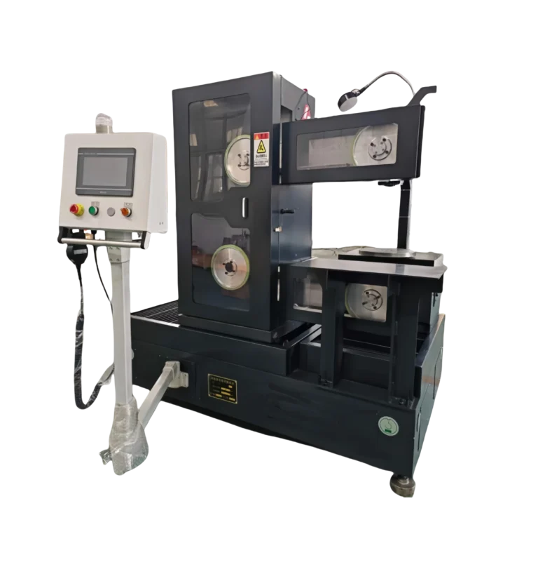
A modern diamond wire saw configured for graphite operates with 0.20–0.25 mm wire, producing kerf widths 50–70% narrower than ID saw blades. In multi-wire configuration, a single machine cuts hundreds of wafers simultaneously from one billet, with each cut maintaining the same narrow kerf.
Practical results we see in graphite slicing applications:
- Kerf loss ratio reduction from 40–50% (ID saw) to 18–22% (multi-wire diamond)
- Wafer yield increase of 25–35% per billet without changing raw material specifications
- Surface quality improvement that reduces downstream lapping by 30–50%
The critical success factor is matching wire parameters (diameter, grit size, tension) to your specific graphite grade. Fine-grained isostatic graphite tolerates the thinnest wire and produces the narrowest kerf. Coarser extruded grades may require slightly thicker wire but still achieve significant improvement over blade-based cutting.
For a complete overview of how kerf loss fits into your overall slicing strategy, see our découpe de graphite de précision guide.