If you’ve been told a wire saw can hold ±0.01 mm on graphite, ask for the data. In our experience running SV60-60 and SH60-60 machines on isostatic and fine-grain graphite, the sustained production tolerance with wire-saw cutting sits at ±0.03 mm — reliably, across a full shift, without babysitting every cut. That is a real number backed by process validation, not a spec sheet aspiration.
The question isn’t just “how accurate can you get?” It’s “how accurate do you need, and what does achieving that cost you in throughput, wire consumption, and process complexity?” Those two questions have different answers depending on whether you’re cutting semiconductor graphite boats, EDM electrodes, or industrial furnace components. This article walks through each accuracy dimension, the parameters that control it, and the honest trade-offs at each precision tier.
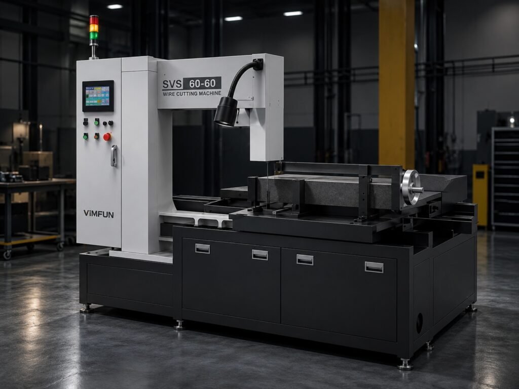
VIMFUN’s SV60-60 and SH60-60 wire saws are the machines this article is built around. Both are purpose-configured for graphite: vertical or horizontal orientation, 0.6–1.0 mm diamond wire, dry cutting (no coolant), and a wire tension range of 150–200 N that keeps dimensional scatter under control batch after batch.
1. Defining Accuracy in Graphite Cutting
Accuracy in graphite cutting is not one number. Buyers and process engineers use the word loosely, and that ambiguity causes misaligned expectations on both sides of a purchase decision. Before specifying a tolerance requirement, it helps to agree on which kind of accuracy you actually mean.
There are three distinct dimensions:
치수 정확도 — the absolute size tolerance on length, width, or thickness. This is what most people mean when they say “±X mm.” It tells you how close the actual cut dimension is to the nominal.
Form accuracy (geometric accuracy) — flatness, parallelism, squareness. A part can be dimensionally within spec but still be out of tolerance on flatness if the cut surface is bowed or if two opposing faces aren’t parallel to each other.
Surface accuracy — surface roughness (Ra) and edge integrity. Graphite is brittle; edge chipping and micro-cracking are real failure modes that dimensional tolerance specs don’t capture.
Wire sawing addresses all three, which is one of the reasons it has displaced band saws and ID saws in demanding graphite applications. For a broader view of how wire cutting compares to other methods, see our guide to 정밀 흑연 슬라이싱 and the comparison of graphite machining alternatives.
Three Practical Accuracy Tiers
Based on application requirements across our installed base, graphite cutting divides into three tiers:
| Tier | Tolerance | Typical Application |
|---|---|---|
| Semiconductor-grade | ±0.01 mm | Graphite boats, susceptor rings for epitaxial deposition |
| EDM-grade | ±0.05 mm | EDM electrodes, precision mold components |
| Industrial-grade | ±0.1 mm | Furnace parts, structural graphite, thermal management blocks |
Wire sawing with the VIMFUN SV60-60 achieves ±0.03 mm in sustained production — which sits between semiconductor-grade and EDM-grade on this table. Reaching ±0.01 mm requires a downstream finish step (typically precision grinding). Attempting it on the wire saw alone without downstream processing is where teams run into inconsistency.
2. What Controls Accuracy in High Accuracy Graphite Cutting
Four factors drive dimensional outcome on a wire saw. Miss any one of them and your tolerance spec becomes a theoretical exercise.
Mechanical System Baseline
The machine’s own positional accuracy sets the floor. Feed axes need sub-micron repeatability; any play in the guide system or wire anchor shows up directly as dimensional scatter. The VIMFUN SV60-60 is built for ±0.03 mm as a sustained production tolerance — meaning the mechanical baseline is tighter than the published spec by enough margin to absorb normal process variation.
One thing that’s easy to underestimate: thermal expansion in the cutting frame. During a long production run, frame temperature can drift by a few degrees. At those scales, thermal expansion of the workpiece fixture itself becomes a non-trivial contributor to dimensional error. This is one reason we recommend letting the machine reach thermal equilibrium before starting a tight-tolerance batch — it’s a 20-minute wait that saves a lot of rework.
Wire Speed: 40–70 m/s
Wire speed affects both material removal rate and surface quality. At the lower end of the range (40–45 m/s), you get more aggressive cutting but a rougher surface and more edge chipping on fine-grain graphite. At the upper end (65–70 m/s), surface quality improves noticeably and edge sharpness is better, but you’re also asking more of the wire over its service life.
For high accuracy graphite cutting, we generally start around 55–60 m/s for isostatic graphite and adjust from there based on material grade. Jumping straight to 70 m/s on a new material without qualification is the kind of shortcut that generates a bad batch at 3 AM.
Feed Rate: 50–100 mm/min
Feed rate is the most direct accuracy lever available to the operator. Slower feed means more wire contact time per unit thickness, finer surface, and less lateral force on the wire — all of which improve dimensional consistency.
The practical lower limit around 50 mm/min is set by productivity. Below that, you’re not making enough progress to justify the machine time. The upper end at 100 mm/min is where you start to see wire bow become significant enough to affect dimensional output on thin slices. For tight-tolerance work (targeting ±0.03 mm sustained), 60–75 mm/min is the sweet spot on most isostatic graphite grades.
Wire Tension: 150–200 N
This is the parameter that gets the least attention and causes the most problems in my experience. Tension controls wire bow under cutting load. Too low, and the wire deflects laterally — your cut plane angles, your dimensional output degrades, and you can’t figure out why because the symptom looks like a calibration problem. Too high, and you’re accelerating wire fatigue. The wire’s rated life of approximately 7 days at 8 hours/day (roughly 56 operating hours) assumes tension stays in the 150–200 N window.
Dry Cutting Strategy
Graphite is cut dry on the SV60-60 and SH60-60 — no liquid coolant. This is a deliberate process choice, not a limitation. Liquid coolant would contaminate the graphite, cause absorption in porous grades, and create graphite-slurry disposal problems. The trade-off is dust management: dry cutting generates fine graphite particulate that requires a dedicated extraction system.
Teams that try to skip the dust extraction step to save setup time discover quickly that accumulated dust in the machine affects wire tracking and can accelerate guide wear. That’s a fixable problem, but it’s not free.
3. Multi-Dimensional Accuracy: Size, Form, and Surface
High accuracy graphite cutting means controlling all three dimensions simultaneously — not just hitting a dimensional number.
Dimensional Accuracy (Size)
On length, width, and thickness, the VIMFUN SV60-60 holds ±0.03 mm in sustained production on isostatic and fine-grain graphite. This applies to cuts from thin wafer slices through thick block sections. The key requirement is that workpiece fixturing is rigid — graphite is light, but vibration from an undersized fixture shows up in dimensional scatter.
Form Accuracy (Flatness and Parallelism)
Wire saws produce flat, parallel cut faces as a natural consequence of the process geometry. The wire moves in a single plane; if the workpiece feed is perpendicular to that plane, the resulting cut faces are parallel to each other and perpendicular to the feed direction.
For low-kerf graphite cutting applications where thin slices are being cut from valuable blocks, this inherent flatness is particularly important: a bowed slice cannot be corrected without additional machining, which defeats the purpose of minimizing kerf loss in the first place.
Practical flatness and parallelism on wire-sawn graphite: flat, uniform faces with no edge chipping — consistent across the cut surface without post-processing.
Surface Quality (Ra and Edge Integrity)
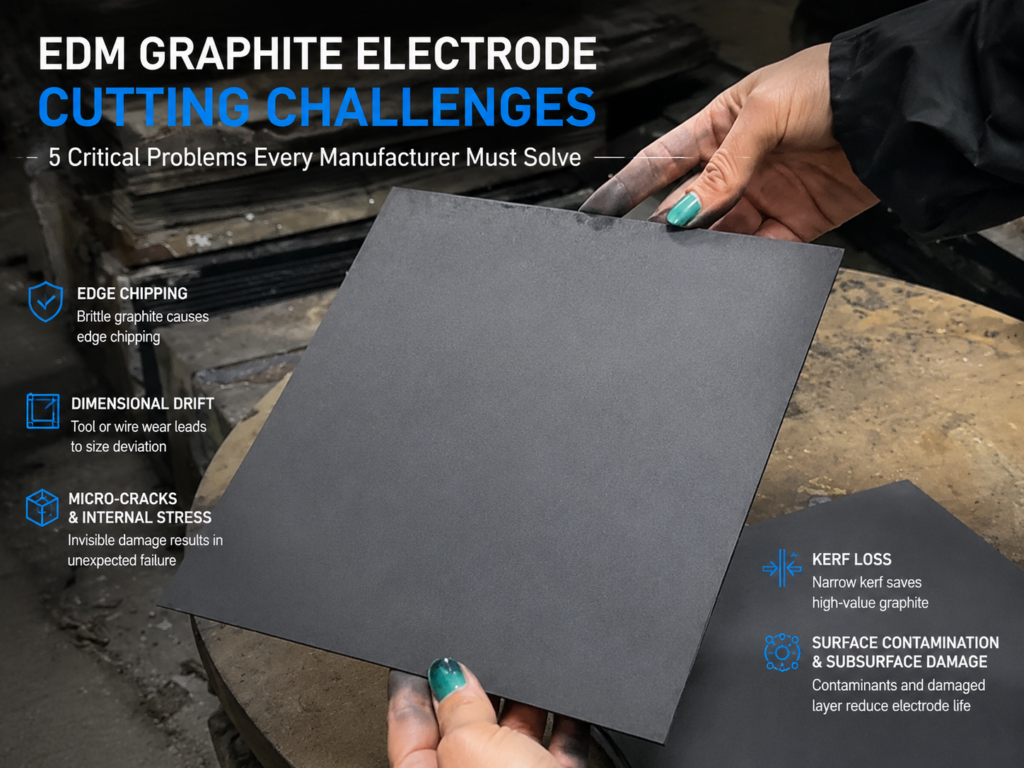
Surface roughness on wire-sawn graphite depends on wire diameter, speed, and feed rate. With 0.6–0.8 mm wire at 55–65 m/s and moderate feed, the resulting surface is smooth and uniform, without the edge microcracks that ID saws and abrasive band saws tend to leave on brittle graphite grades.
Edge chipping — the failure mode where corners and edges break away during or after cutting — is essentially eliminated at the recommended parameters. This matters most for semiconductor graphite boats, where edge integrity affects how the boat handles wafer loading without generating particles.
Wire diameter selection has a direct effect on surface quality and is worth discussing explicitly. A 0.6 mm wire produces a narrower kerf (less material loss) and a finer surface finish, but it is more sensitive to tension and feed rate variation — the tolerance window for correct process setup is narrower. A 1.0 mm wire is more forgiving, tolerates slightly faster feed, and is better suited to larger workpieces where stiffness helps maintain wire tracking. For high accuracy graphite cutting where surface quality is the priority, 0.6–0.8 mm is the typical selection range. For applications where throughput matters more than ultimate surface quality, 0.8–1.0 mm makes more sense.
One limitation worth naming: surface roughness from wire sawing alone is typically not at the level required for polished optical or precision contact surfaces. If a very low Ra value is required after cutting, a lapping or grinding step will still be needed. Wire sawing gets you close; it does not replace surface finishing for the highest-spec graphite components. This is an honest constraint, and any process that claims otherwise should be asked for Ra data across a production batch.
4. Maintaining Accuracy in High Accuracy Graphite Cutting Across Long Runs
One-off accuracy is relatively straightforward. Sustained accuracy across a production batch of 50 or 500 pieces is the harder problem, and it’s where equipment quality and process discipline separate the workable approaches from the ones that fail in production.
Wire Diameter Wear and Compensation
Diamond wire wears over its service life. As the wire diameter decreases, kerf width decreases — which sounds like it would improve material yield, but actually introduces a dimensional drift if the wire compensation isn’t tracked. A wire that started at 0.8 mm and has worn to 0.72 mm will produce parts that are systematically different from the specification if no compensation is applied.
The VIMFUN SV60-60 tracks wire wear and allows offset compensation. The wire’s service life is approximately 7 days at 8 hours/day — after which replacement is required regardless of apparent condition, because fatigue accumulation in the wire core isn’t visible. Teams that try to extend wire life beyond this window to save consumable cost typically discover the problem in a batch of out-of-spec parts, not before.
Batch-to-Batch Consistency
The factors that affect batch consistency are: wire condition (age, accumulated wear), fixture condition (clamping force, thermal state), and room temperature if ambient swings are large. In a controlled production environment, these are manageable. In an uncontrolled one, dimensional scatter of ±0.05 mm or worse becomes common even on a machine capable of ±0.03 mm.
Repeatability — the ability to return to the same dimensional output on a new batch with fresh wire — is where machine quality shows. On the SV60-60, positional repeatability is tight enough that batch-to-batch dimensional variation is dominated by process inputs (wire condition, fixturing), not machine variation.
Fixture Design Is Underrated
The workpiece fixture doesn’t move — but its design directly affects the cut. Graphite is soft enough that clamping pressure can cause micro-distortion in the workpiece, particularly in thin sections. If the part is distorted in the fixture during cutting and then springs back when unclamped, what measured as in-tolerance on the machine can come out of tolerance in inspection. This is one of those issues that bites teams who adapt fixtures from harder materials without rechecking clamp force limits.
동일한 흑연 부품을 반복적으로 생산하는 경우, 클램핑 하중을 올바르게 분산시키는 맞춤형 고정구에 투자하면 빠르게 수익을 회수할 수 있습니다. 이는 기계 사양에는 나타나지 않지만 지속적인 치수 출력에 측정 가능한 영향을 미치는 종류의 세부 사항입니다. VIMFUN의 애플리케이션 엔지니어링 팀은 일반적으로 첫 생산 전에 고객 고정구 설계를 검토하며, 이는 형식적인 절차가 아닙니다.
애플리케이션 요구 사항: 고정밀 흑연 절단이 가장 중요한 곳
다양한 애플리케이션은 절단 공정에 대해 서로 다른 것을 요구합니다. 한 애플리케이션에 중요한 공차 요구 사항이 다른 애플리케이션에는 관련이 없으며, 이를 이해하는 것이 더 나은 장비 선택 결정을 내리는 데 도움이 됩니다.
각 애플리케이션의 위치 vs. 관련 페이지
| 애플리케이션 | 공차 요구 사항 | 주요 제약 조건 | 관련 페이지 |
|---|---|---|---|
| 반도체 흑연 보트 | ±0.01–0.03 mm | 모서리 무결성, 입자 발생 | 흑연 보트 절단 |
| EDM 전극 | ±0.05 mm | EDM 스파크 갭을 위한 형상 정확도, 표면 마감 | EDM graphite electrode cutting |
| 산업용 로 부품 | ±0.1 mm | 처리량, 비용, 재료 활용도 | 일반 절단 페이지 |
| 얇은 슬라이스 / 웨이퍼 | ±0.03 mm + 평탄도 | 절단 손실, 평탄도 | low-kerf graphite cutting |
반도체 흑연 보트 — 최고 정밀도
흑연 보트 절단 반도체 애플리케이션용은 정밀도 피라미드의 최상위에 있습니다. CVD, 에피택셜 성장 및 확산 로에 사용되는 보트는 웨이퍼를 측면 유격 없이 수용하기 위해 엄격한 슬롯 치수를 유지해야 하며, 동시에 공정 챔버 내부에서 입자 발생을 방지하기 위해 모서리 무결성을 유지해야 합니다.
SV60-60을 사용한 와이어톱 절단은 이러한 부품에 필요한 평평하고 칩이 없는 표면을 생성합니다. 와이어톱에서 ±0.03mm의 치수 공차, 그 다음 ±0.01mm가 필요한 정밀 연삭은 대부분의 자격을 갖춘 제조업체가 사용하는 2단계 공정입니다.
EDM 전극 — 형상 및 표면이 중요
EDM graphite electrode cutting operates at ±0.05 mm tolerance in most cases. The geometry of the electrode directly determines the shape burned into the workpiece — a twisted or bowed electrode face creates a distorted cavity. Wire sawing is well-suited here because the resulting faces are flat and the cut angles are controlled.
Surface roughness also matters for EDM: a smoother electrode surface produces a more predictable spark gap. Wire-sawn graphite surfaces are suitable for most EDM applications without additional finish grinding.
Industrial Graphite Components
At the industrial end — furnace parts, heat shields, structural blocks — the tolerance requirement relaxes to ±0.1 mm or wider. Here the economic driver shifts: throughput and material utilization matter more than dimensional perfection. Wire sawing is still used for low-kerf graphite cutting to maximize material yield from expensive graphite stock, but the accuracy bar is more forgiving.
6. The Economics of Accuracy: When Tighter Isn’t Better
There is a cost curve attached to every tolerance tier. The relationship is not linear: going from ±0.1 mm to ±0.05 mm costs a moderate increment. Going from ±0.05 mm to ±0.01 mm costs a large increment. Going below ±0.01 mm costs an enormous increment that most applications cannot justify.
The Cost Components of Tight Tolerance
Throughput. 더 느린 이송 속도는 더 엄격한 공차를 위해 시간당 생산량을 줄입니다. 60mm/min 대 100mm/min에서는 동일한 기계에서 40% 낮은 처리량을 받아들이는 것입니다.
와이어 소모량. 더 엄격한 공차 작업은 마모로 인한 치수 드리프트를 피하기 위해 더 보수적인 와이어 교체 간격을 요구하는 경우가 많습니다. 와이어는 상당한 소모품 비용입니다.
공정 엔지니어링 시간. ±0.03mm를 일관되게 달성하려면 공정 자격이 필요합니다: 파라미터 개발, 고정구 설계, 열 관리. 그 작업은 실질적이며 선행됩니다.
다운스트림 작업. ±0.01mm에 도달하려면 일반적으로 와이어 절단 후 정밀 연삭이 필요합니다. 단일 작업 비용 대 이중 작업 비용.
±0.03mm가 정답일 때
대부분의 EDM 전극 응용 분야와 상당수의 반도체 흑연 보트 러핑의 경우, ±0.03mm 와이어 절단 출력은 후속 연삭 단계를 없애줍니다. 이것이 이러한 응용 분야에서 SV60-60의 경제적 이점입니다. 이는 완전한 작업이 될 만큼 충분한 정확도를 제공하며 사전 처리 단계가 아닙니다.
만약 귀하의 응용 분야가 예외 없이 진정으로 ±0.01mm를 요구한다면, 2단계 공정을 계획하십시오. 만약 ±0.05mm를 요구한다면, ±0.03mm 목표가 허용하는 것보다 더 빠르게 작동하고 더 나은 처리량을 얻을 수 있을 것입니다. 사양 문서에 인상적으로 들리는 가장 엄격한 수치가 아니라 부품이 실제로 필요로 하는 공차 요구 사항을 사용하십시오.
다양한 공차 등급에서 와이어 절단을 다른 방법과 비교하는 것은 다음에서 더 자세히 다룹니다. graphite machining alternatives.
FAQ
Q: 고정밀 흑연 절단을 위한 달성 가능한 공차는 얼마입니까?
VIMFUN SV60-60 또는 SH60-60 기계로 등방성 및 미세 입자 흑연의 지속적인 생산 공차는 ±0.03mm입니다. 이는 치수 정확도(길이, 너비, 두께)에 적용됩니다. ±0.01mm에 도달하려면 와이어 절단 후 다운스트림 정밀 연삭 단계가 필요합니다.
Q: 고정밀 흑연 절단에 냉각수가 필요합니까?
아니요. SV60-60 및 SH60-60은 흑연을 건식으로 절단합니다 - 액체 냉각수 없음. 흑연은 액체를 흡수하며 건식 절단은 오염을 방지합니다. 요구 사항은 미세 흑연 입자를 처리하기 위한 전용 집진 시스템입니다.
Q: 고정밀 흑연 절단에서 와이어 장력이 절단 정확도에 어떤 영향을 미칩니까?
와이어 장력은 절단 하중 하에서 와이어의 휨을 직접 제어합니다. 올바른 범위(SV60-60/SH60-60에서 150–200N)에서는 측면 편향이 최소화되고 치수 출력이 일관됩니다. 장력이 너무 낮으면 휨이 발생하여 치수 또는 형상 오류로 나타납니다. 종종 보정 문제로 오인됩니다.
Q: 고정밀 흑연 절단 응용 분야에서 다이아몬드 와이어의 수명은 얼마나 됩니까?
권장 매개변수로 흑연에서 하루 8시간씩 약 7일 동안 와이어 수명이 지속됩니다. 이 기간이 지나면 와이어 코어의 피로 누적으로 인해 와이어가 손상되지 않은 것처럼 보여도 파손 위험이 발생합니다. 일정을 잡은 간격으로 와이어를 교체하는 것은 일관된 고정밀 흑연 절단 결과를 유지하는 부분입니다.
Q: VIMFUN SV60-60 또는 SH60-60 중 어떤 것이 반도체 흑연 부품에 더 적합합니까?
두 기계 모두 흑연용으로 구성되었으며 동일한 ±0.03mm 정확도를 제공합니다. SV60-60은 수직 이송 방향을 처리하여 더 큰 작업물과 특정 블록 형상에 적합합니다. SH60-60은 수평 이송 방향을 사용합니다. 선택은 작업물 형상 및 고정 선호도에 따라 달라집니다. VIMFUN에 문의하십시오. daria@endlesswiresaw.com 특정 응용 분야에 대한 권장 사항을 받으십시오.
절단 정확도 시험 요청
생산 공정에 투입하기 전에 흑연 부품의 공차 검증이 필요한 경우, VIMFUN은 SV60-60 및 SH60-60에서 절단 시험을 제공합니다. 재료 등급, 치수 및 공차 요구 사항을 다음으로 보내주십시오. daria@endlesswiresaw.com — 응용 분야 팀이 실현 가능성을 확인하고 시험 매개변수를 정의합니다.
VIMFUN 소개
VIMFUN은 흑연, 고급 세라믹, 광학 유리, 반도체 재료 및 기타 단단하고 부서지기 쉬운 재료를 위한 무한 다이아몬드 와이어 절단을 전문으로 합니다. 기계에는 흑연 응용 분야를 위한 SV60-60 및 SH60-60이 포함됩니다. 자세한 내용은 다음에서 확인하십시오. graphitecutting.com.
저자 소개
VIMFUN 응용 분야 엔지니어링 팀 작성 — 반도체, EDM 및 산업용 흑연 응용 분야를 위한 정밀 절단 공정 개발 전문가.