
You can slice graphite all day long, but if the thickness varies by 0.3 mm from one plate to the next — or worse, across a single plate — your downstream process pays the price. Grinding takes longer, material gets wasted, and reject rates climb.
Graphite slicing thickness control is the single most important quality metric in plate production. Get it right, and you ship plates that go straight into assembly with minimal finishing. Get it wrong, and every plate needs extra grinding to hit spec — eating into your margins and your lead time.
Why Graphite Slicing Thickness Control Matters
The Cost of Poor Thickness Control
When a graphite plate comes off the wire saw at 5.2 mm instead of 5.0 mm, that extra 0.2 mm has to be ground away. On a 200 × 100 mm plate, that’s approximately 2.5 cm³ of wasted graphite. At $50–$200/kg for isostatic grades, the material cost adds up fast across hundreds of plates.
But material waste isn’t the biggest cost. It’s the grinding time. Double-sided lapping or surface grinding runs at fixed removal rates. An extra 0.2 mm per plate might add 30–60 seconds of grinding time per piece. Over a production run of 1,000 plates, that’s 8–16 hours of additional machine time — directly reducing your output capacity.
Typical Tolerance Requirements
| 애플리케이션 | Thickness Tolerance | 왜 |
|---|---|---|
| Fuel cell bipolar plates | ±0.05 mm | Stack compression uniformity |
| EDM electrode blanks | ±0.1 mm | Consistent spark gap |
| Semiconductor wafer chucks | ±0.02 mm | Wafer flatness transfer |
| Heat spreaders | ±0.1 mm | Thermal interface contact |
| Heating elements | ±0.15 mm | Resistance consistency |
The tighter the tolerance, the more critical your graphite slicing thickness control becomes — and the less room you have for process variation.
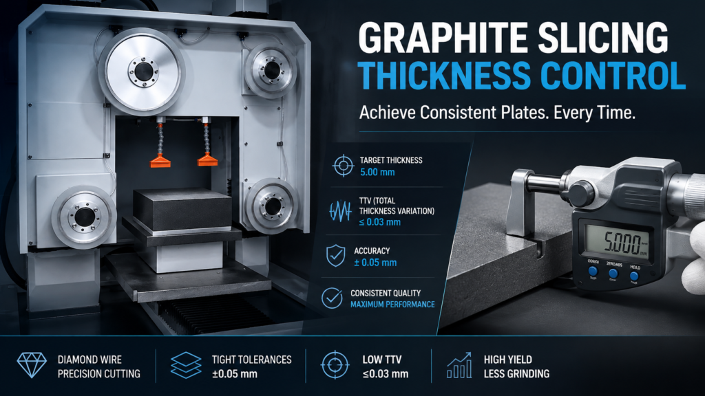
What Causes Thickness Variation in Graphite Slicing
Understanding the sources of variation is the first step to controlling them. There are five primary causes:
1. Wire Deflection During Cutting
This is the most common cause of thickness variation. As the diamond wire cuts through the graphite block, cutting forces push the wire sideways. The wire bows in the middle of the cut, producing a plate that’s thinner at the center than at the edges.
Wire deflection increases with:
- Higher feed rate (more cutting force)
- Lower wire tension (less resistance to deflection)
- Longer cut length (more wire span to bow)
- Worn diamond coating (higher friction)
A plate cut from a 200 mm wide block will show more center-to-edge variation than one cut from a 50 mm block — simply because the wire has more length to deflect.
2. Block Fixturing Problems
If the graphite block moves during cutting — even 0.05 mm — that movement transfers directly into the plate thickness. Common fixturing issues:
- Insufficient clamping force. Graphite is porous and doesn’t grip as well as metal. Standard vise clamping may not hold under cutting forces.
- Adhesive bond failure. When blocks are glued to the work table, incomplete adhesive coverage or weak bond strength allows micro-movement.
- Thermal expansion. The block and fixture expand at different rates during extended cutting. Without compensation, this introduces progressive thickness drift across a batch.
3. Wire Wear and Degradation
Diamond wire doesn’t cut at constant efficiency. As the diamond abrasive wears, cutting force increases for the same feed rate. This causes:
- Gradually increasing wire deflection over the wire’s service life
- First plates in a batch cut slightly differently from the last plates
- Sudden changes in cutting behavior when heavily worn sections of wire enter the cut zone
Monitoring wire condition and replacing wire at consistent intervals — not when it breaks — is essential for graphite slicing thickness control across large batches.
4. Graphite Density Variation
Graphite blocks are not perfectly homogeneous. Even isostatic-pressed graphite from manufacturers like SGL Carbon has density variations of 1–3% within a single block. Higher density zones resist cutting, causing the wire to deflect more. Lower density zones cut faster, potentially causing the wire to advance too quickly.
The result is thickness variation that follows the density pattern of the block — something you can’t control, only compensate for.
열 효과
와이어와 흑연 사이의 마찰은 열을 발생시킵니다. 이 열은 다음을 유발합니다:
- 와이어 열팽창 (유효 장력 변경)
- 블록 열팽창 (절단 위치 변경)
- 냉각수 점도 변화 (윤활에 영향)
이러한 열 효과는 절단 중에 누적됩니다. 큰 블록을 30분 동안 절단하는 것은 작은 블록을 5분 동안 절단하는 것보다 더 많은 열 드리프트를 유발합니다.
흑연 슬라이싱 두께 제어 개선 방법
와이어 장력 최적화
와이어 장력은 흑연 슬라이싱 두께 제어에 가장 효과적인 레버입니다. 장력이 높을수록 와이어 처짐이 줄어들어 더 일관된 판 두께를 얻을 수 있습니다. 하지만 한계가 있습니다. 너무 높으면 와이어가 끊어지거나 조기에 피로해집니다.
최적의 접근 방식은 서보 제어 장력 절단 내내 일정한 힘을 유지합니다. 이는 와이어 늘어남, 열팽창 및 스풀 직경 변화를 자동으로 보상합니다. 수동 장력 조정으로는 이러한 일관성을 맞출 수 없습니다.
적응형 피드 제어 사용
고정된 피드 속도를 실행하는 대신, 적응형 제어는 실시간 절단 저항을 기반으로 피드 속도를 조정합니다.
| Condition | 적응형 응답 | 두께 이점 |
|---|---|---|
| 와이어가 더 밀집된 영역으로 들어감 | 피드 속도 감소 | 와이어 처짐 감소 |
| 와이어가 더 부드러운 영역으로 들어감 | 피드 속도 증가 | 와이어 흔들림 방지 |
| 와이어가 절단 끝에 접근함 | 피드 속도 늦춤 | 더 깨끗한 종료, 칩핑 감소 |
| 냉각수 흐름 감소 | 피드 일시 중지 | 열 손상 방지 |
이는 내부 밀도 변화 때문에 흑연에 특히 중요합니다. 2% 밀도 변화가 있는 블록을 고정된 피드 속도로 절단하면 측정 가능한 두께 차이가 발생합니다. 적응형 제어는 이를 최소화합니다.
냉각수 공급 제어
일관된 냉각수 흐름은 잔해물을 씻어내는 것 이상을 합니다. 이는 다음을 수행합니다.
- 절단 영역에서 안정적인 온도 유지
- 일관된 윤활 제공 (절단력에 영향)
- 긴 절단 중 열 드리프트 방지
흑연 슬라이싱 두께 제어의 경우 냉각수 유량 및 온도를 모니터링하고 일정하게 유지해야 합니다. 냉각수 시스템이 재순환하는 경우, 생산 교대 중에 냉각수 온도가 ±2°C 이상으로 벗어나지 않는지 확인하십시오.
통계적 공정 제어 구현
모든 판을 측정하는 것만으로는 충분하지 않습니다. 추세를 추적해야 합니다.
- 판당 3-5개 지점(중앙, 네 모서리)에서 두께 측정
- 절단 시퀀스당 값 기록
- 배치 실행 동안 추세 플로팅
- 제어 한계 설정 (예: 목표값 ±0.05mm)
- 추세가 제어 한계에 접근하면 수정 조치(와이어 교체, 장력 조정, 냉각수 확인)를 취하십시오.
이는 규격 외 판을 생성하기 전에 점진적인 드리프트를 포착합니다. 반응적 검사(배치가 완료된 후 측정)는 불량품을 찾지만 예방하지는 못합니다. 수동 검사 중 흑연 먼지 노출도 다음을 준수해야 합니다. OSHA 허용 노출 한계.
와이어 직경을 판 두께에 맞추기
일반적인 실수는 모든 작업에 동일한 와이어를 사용하는 것입니다. 얇은 판( 10mm)의 경우 더 두꺼운 와이어(0.5-0.65mm)를 사용하십시오. 와이어 직경은 강성에 영향을 미칩니다. 더 두꺼운 와이어는 덜 휘지만 더 넓은 커프를 절단합니다.
목표는 필요한 강성에 충분한 와이어 강성을 찾는 균형점을 찾는 것입니다. graphite slicing thickness control 과도한 kerf loss.
흑연 슬라이싱 두께 제어 측정
권장 측정 방법
| Measurement | 도구 | Resolution |
|---|---|---|
| 판 두께 (단일 지점) | 디지털 마이크로미터 | 0.001 mm |
| 두께 맵 (다중 지점) | CMM 또는 XY 스테이지가 있는 두께 게이지 | 0.001 mm |
| TTV (총 두께 편차) | 전체 표면에 걸친 자동 게이지 | 0.001 mm |
| 공정 중 모니터링 | 레이저 변위 센서 | 0.01 mm |
TTV (총 두께 편차)는 흑연 슬라이싱 두께 제어에 가장 의미 있는 단일 숫자입니다. 단일 판에서 가장 두꺼운 지점과 가장 얇은 지점 간의 최대 차이를 포착합니다. 0.03mm의 TTV는 우수하며, 0.1mm는 대부분의 응용 분야에서 허용 가능하며, 0.2mm 이상은 공정 문제를 나타냅니다.
두께 제어를 전체 공정에 연결
흑연 슬라이싱 두께 제어는 독립적으로 존재하지 않습니다. 다음 사항과 직접 연결됩니다.
- 슬라이싱 공정 — 절단 매개변수는 초기 두께 정확도를 결정합니다.
- Flatness and parallelism — 판은 평균적으로 목표 두께에 도달할 수 있지만 여전히 쐐기 모양일 수 있습니다.
- 결함 — 가장자리 칩핑은 판 가장자리의 사용 가능한 두께를 효과적으로 줄입니다.
- Kerf loss — 더 넓은 커프는 절단 계획에서 오류의 여지를 줄입니다.
이러한 모든 품질 요소가 어떻게 함께 작동하는지에 대한 개요는 당사의 정밀 흑연 슬라이싱 pillar guide.


