You can slice graphite all day long, but if the thickness varies by 0.3 mm from one plate to the next — or worse, across a single plate — your downstream process pays the price. Grinding takes longer, material gets wasted, and reject rates climb.
Graphite slicing thickness control is the single most important quality metric in plate production. Get it right, and you ship plates that go straight into assembly with minimal finishing. Get it wrong, and every plate needs extra grinding to hit spec — eating into your margins and your lead time.
Why Graphite Slicing Thickness Control Matters
The Cost of Poor Thickness Control
When a graphite plate comes off the wire saw at 5.2 mm instead of 5.0 mm, that extra 0.2 mm has to be ground away. On a 200 × 100 mm plate, that’s approximately 2.5 cm³ of wasted graphite. At $50–$200/kg for isostatic grades, the material cost adds up fast across hundreds of plates.
But material waste isn’t the biggest cost. It’s the grinding time. Double-sided lapping or surface grinding runs at fixed removal rates. An extra 0.2 mm per plate might add 30–60 seconds of grinding time per piece. Over a production run of 1,000 plates, that’s 8–16 hours of additional machine time — directly reducing your output capacity.
Typical Tolerance Requirements
| Application | Thickness Tolerance | Why |
|---|---|---|
| Fuel cell bipolar plates | ±0.05 mm | Stack compression uniformity |
| EDM electrode blanks | ±0.1 mm | Consistent spark gap |
| Semiconductor wafer chucks | ±0.02 mm | Wafer flatness transfer |
| Heat spreaders | ±0.1 mm | Thermal interface contact |
| Heating elements | ±0.15 mm | Resistance consistency |
The tighter the tolerance, the more critical your graphite slicing thickness control becomes — and the less room you have for process variation.
What Causes Thickness Variation in Graphite Slicing
Understanding the sources of variation is the first step to controlling them. There are five primary causes:
1. Wire Deflection During Cutting
This is the most common cause of thickness variation. As the diamond wire cuts through the graphite block, cutting forces push the wire sideways. The wire bows in the middle of the cut, producing a plate that’s thinner at the center than at the edges.
Wire deflection increases with:
- Higher feed rate (more cutting force)
- Lower wire tension (less resistance to deflection)
- Longer cut length (more wire span to bow)
- Worn diamond coating (higher friction)
A plate cut from a 200 mm wide block will show more center-to-edge variation than one cut from a 50 mm block — simply because the wire has more length to deflect.
2. Block Fixturing Problems
If the graphite block moves during cutting — even 0.05 mm — that movement transfers directly into the plate thickness. Common fixturing issues:
- Insufficient clamping force. Graphite is porous and doesn’t grip as well as metal. Standard vise clamping may not hold under cutting forces.
- Adhesive bond failure. When blocks are glued to the work table, incomplete adhesive coverage or weak bond strength allows micro-movement.
- Thermal expansion. The block and fixture expand at different rates during extended cutting. Without compensation, this introduces progressive thickness drift across a batch.
3. Wire Wear and Degradation
Diamond wire doesn’t cut at constant efficiency. As the diamond abrasive wears, cutting force increases for the same feed rate. This causes:
- Gradually increasing wire deflection over the wire’s service life
- First plates in a batch cut slightly differently from the last plates
- Sudden changes in cutting behavior when heavily worn sections of wire enter the cut zone
Monitoring wire condition and replacing wire at consistent intervals — not when it breaks — is essential for graphite slicing thickness control across large batches.
4. Graphite Density Variation
Graphite blocks are not perfectly homogeneous. Even isostatic-pressed graphite from manufacturers like SGL Carbon has density variations of 1–3% within a single block. Higher density zones resist cutting, causing the wire to deflect more. Lower density zones cut faster, potentially causing the wire to advance too quickly.
The result is thickness variation that follows the density pattern of the block — something you can’t control, only compensate for.
5. Thermal Effects
Friction between the wire and graphite generates heat. This heat causes:
- Wire thermal expansion (changes effective tension)
- Block thermal expansion (changes cut position)
- Coolant viscosity changes (affects lubrication)
These thermal effects are cumulative during a cut. A 30-minute cut through a large block will have more thermal drift than a 5-minute cut through a small block.
How to Improve Graphite Slicing Thickness Control
Optimize Wire Tension
Wire tension is the most effective lever for graphite slicing thickness control. Higher tension reduces wire deflection, producing more consistent plate thickness. But there’s a limit — too high and the wire breaks or fatigues prematurely.
The optimal approach is servo-controlled tension that maintains constant force throughout the cut. This compensates for wire stretch, thermal expansion, and spool diameter changes automatically. Manual tension adjustment can’t match this consistency.
Use Adaptive Feed Control
Instead of running a fixed feed rate, adaptive control adjusts feed speed based on real-time cutting resistance:
| Condition | Adaptive Response | Thickness Benefit |
|---|---|---|
| Wire enters denser zone | Reduces feed rate | Less wire deflection |
| Wire enters softer zone | Increases feed rate | Prevents wire wander |
| Wire approaching end of cut | Slows feed | Cleaner exit, less chipping |
| Coolant flow drops | Pauses feed | Prevents thermal damage |
This is especially important for graphite because of its internal density variations. A fixed feed rate through a block with 2% density variation will produce measurable thickness differences. Adaptive control minimizes this.
Control Coolant Delivery
Consistent coolant flow does more than flush debris. It:
- Maintains stable temperature at the cut zone
- Provides consistent lubrication (affecting cutting force)
- Prevents thermal drift during long cuts
For graphite slicing thickness control, coolant flow rate and temperature should be monitored and held constant. If your coolant system recirculates, check that the coolant temperature doesn’t drift more than ±2°C during a production shift.
Implement Statistical Process Control
Measuring every plate isn’t enough — you need to track the trend:
- Measure thickness at 3–5 points per plate (center, four edges)
- Record the values per cut sequence
- Plot the trend over a batch run
- Set control limits (e.g., ±0.05 mm from target)
- When the trend approaches a control limit, take corrective action (wire replacement, tension adjustment, coolant check)
This catches gradual drift before it produces out-of-spec plates. Reactive inspection (measure after the batch is done) finds rejects but doesn’t prevent them. Graphite dust exposure during manual inspection should also comply with OSHA permissible exposure limits.
Match Wire Diameter to Plate Thickness
A common mistake is using the same wire for all jobs. For thin plates (< 3 mm), use thinner wire (0.3–0.4 mm). For thick plates (> 10 mm), use thicker wire (0.5–0.65 mm). The wire diameter affects rigidity — thicker wire deflects less but cuts a wider kerf.
The goal is finding the balance point where wire rigidity is sufficient for the required graphite slicing thickness control without excessive kerf loss.
Measuring Graphite Slicing Thickness Control
Recommended Measurement Method
| Measurement | Tool | Resolution |
|---|---|---|
| Plate thickness (single point) | Digital micrometer | 0.001 mm |
| Thickness map (multi-point) | CMM or thickness gauge with XY stage | 0.001 mm |
| TTV (Total Thickness Variation) | Automated gauge across full surface | 0.001 mm |
| In-process monitoring | Laser displacement sensor | 0.01 mm |
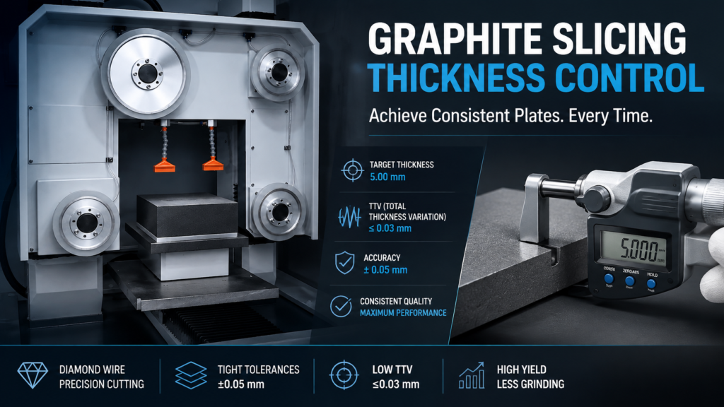
TTV (Total Thickness Variation) is the most meaningful single number for graphite slicing thickness control. It captures the maximum difference between the thickest and thinnest point on a single plate. A TTV of 0.03 mm is excellent; 0.1 mm is acceptable for most applications; above 0.2 mm indicates a process problem.
Connecting Thickness Control to the Full Process
Graphite slicing thickness control doesn’t exist in isolation. It connects directly to:
- The slicing process — your cutting parameters determine initial thickness accuracy
- Flatness and parallelism — a plate can hit target thickness on average but still be wedge-shaped
- Defects — edge chipping effectively reduces usable thickness at the plate edges
- Kerf loss — wider kerf means less room for error in the cutting plan
For an overview of how all these quality factors work together, see our precision graphite slicing pillar guide.