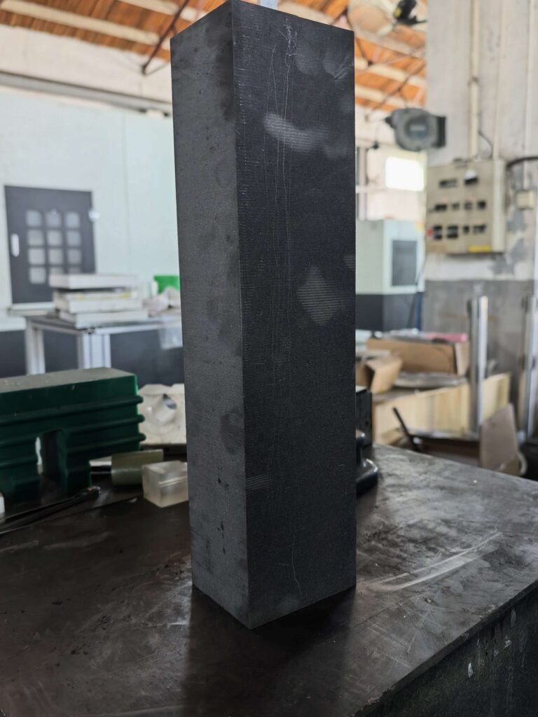
Take a 100 mm cutting length and divide it into nominal 5 mm slices. With an assumed 1.0 mm kerf, the geometry allows 16 complete slices; with an assumed 0.5 mm kerf, it allows 18. That is a geometry example, not a production benchmark, but it shows why the low kerf vs wide kerf graphite decision can change the number of saleable parts recovered from the same block.
It does not prove that the narrower process is cheaper.
Low kerf reduces material removed by each cut. Wide kerf may provide a less sensitive process window on a difficult grade, deep section, or unstable setup. If the low-kerf run adds wire breaks, dimensional rejects, slower feed, or more inspection, the recovered material can be consumed by operating cost. The right comparison is therefore not nominal wire diameter or kerf width alone. It is total cost per accepted part at batch level.
This guide defines that decision boundary. For parameter-level actions, use the guide to reducing kerf loss in graphite cutting. For procurement-level recovery calculations, use the separate graphite material utilization rate analysis.
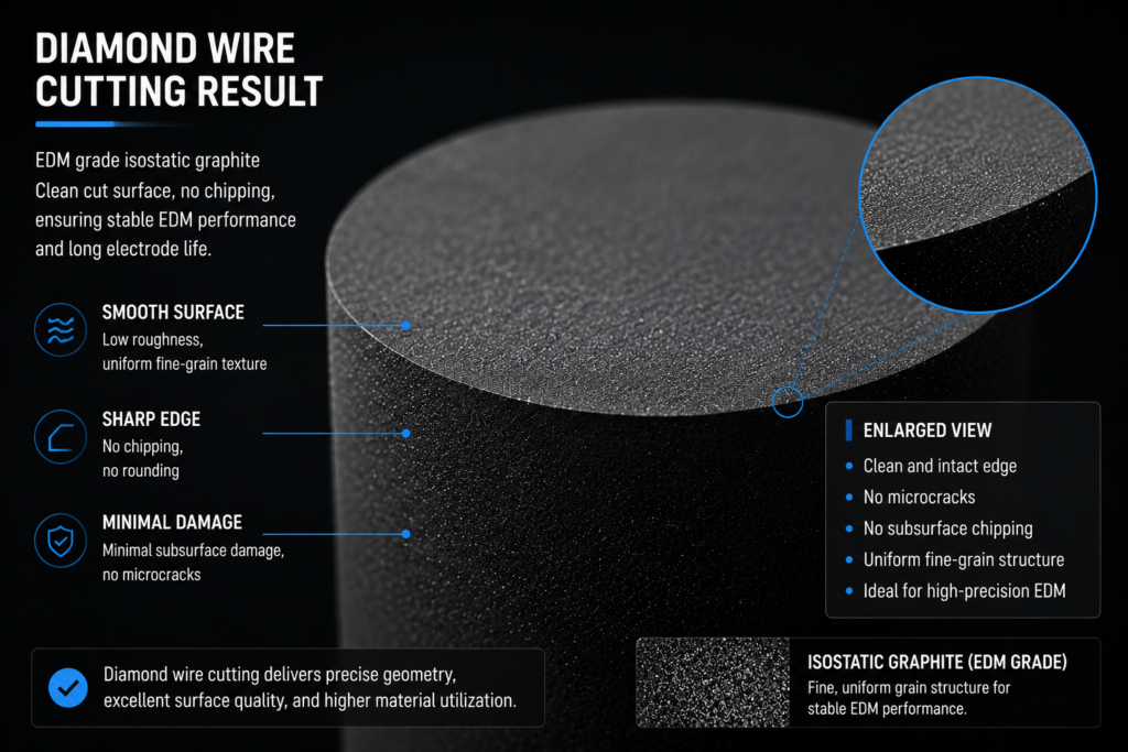
What “Low Kerf” and “Wide Kerf” Actually Mean
Low and wide are relative terms. A kerf is low only when compared with the current qualified process for the same graphite grade, block depth, part geometry, and acceptance criteria. A nominal wire specification is not enough.
The measured cut is normally wider than the wire body because the abrasive envelope, wire motion, runout, debris, and local material removal all contribute to the effective kerf. Experimental diamond-wire studies on other brittle materials have measured kerf beyond the wire envelope and linked the difference to lateral swing and vibration. Those results should not be copied as graphite benchmarks, but the mechanism is relevant: a thinner wire does not guarantee a proportionally narrower production kerf.
For a valid low kerf vs wide kerf graphite comparison, define both processes using the actual kerf distribution across accepted production cuts:
- Mean kerf width
- Kerf variation along the cut
- Kerf drift over wire life
- Dimensional acceptance rate
- Surface condition after cutting
If those five items are missing, the team is comparing tool labels, not production processes.
Low Kerf vs Wide Kerf Graphite: Decision Matrix
| Decision factor | Low-kerf process | Wider-kerf process | What decides the winner |
|---|---|---|---|
| Material removed per cut | Lower when the measured kerf remains stable | Higher by geometry | Actual kerf, not nominal wire diameter |
| Parts recovered per block | Can increase on thin slices or high cut-count layouts | Usually lower on the same layout | Part thickness, cut count, trim, and nesting |
| Process sensitivity | Often more sensitive to deviation and wear | May tolerate a broader operating window | Grade, block depth, fixture, and monitoring capability |
| Dimensional consistency | Strong when the process is qualified | Can be easier to hold in difficult conditions | Batch distribution, not the best individual part |
| Surface and edge condition | Not automatically better | Not automatically worse | Cutting force, vibration, feed, wire condition, and material structure |
| Cycle time | May increase if feed must be reduced | May support a more forgiving production rate | Accepted parts per hour |
| Validation burden | Higher when replacing a stable baseline | Lower when already qualified | Cost of trials, inspection, and process approval |
| Best fit | Expensive grades, thin parts, repeat batches, many cuts | Prototypes, deep sections, unstable geometries, low-value material | Total cost per accepted part |
The table is deliberately conditional. “Low kerf saves material” is true at the cut level. “Low kerf saves money” is only true after the process holds acceptance rate and production stability.
The Cost Model That Prevents the Wrong Decision
A useful comparison has four cost buckets:
- Input material cost — full block cost allocated to the job.
- Cutting cost — machine time, labor, wire consumption, coolant or dust control, and setup.
- Quality cost — inspection, rework, rejected parts, and downstream stock removal.
- Interruption cost — wire breaks, restart time, lost cuts, schedule disruption, and repeat qualification.
Then calculate:
Total cost per accepted part = (material + cutting + quality + interruption costs) / accepted parts
This denominator matters. Cost per cut can make a faster wide-kerf process look attractive even when it produces fewer parts per block. Material recovery alone can make a low-kerf process look attractive even when it produces too many rejects. Cost per accepted part forces both effects into the same decision.
Do not insert a generic “low kerf saves 20%” claim into the business case. The saving depends on part thickness, number of cuts, block price, measured kerf difference, acceptance rate, and process time. Without those inputs, the percentage is sales language, not engineering evidence.
For the arithmetic behind material recovery, see graphite material utilization rate. For the distinction between recovered material and accepted output, see graphite cutting yield improvement.
When Low Kerf Usually Wins
Low kerf has the strongest economic case when material value and cut count are both high. Each avoided fraction of kerf repeats across the block, so the recovery effect compounds as the number of slices increases.
Four conditions make the case stronger:
- The graphite grade is expensive. The same recovered volume carries more financial value.
- The parts are thin. Kerf occupies a larger share of the pitch between adjacent parts.
- The production run repeats. Qualification cost can be spread across many accepted parts.
- The process is measurable. The team can track kerf drift, dimensional distribution, wire condition, and rejects rather than relying on a first-piece result.
Under those conditions, the low-kerf option can improve both recovery and delivered-part cost. It also creates more layout flexibility: recovered stock may become another complete part instead of an unusable remainder.
But there is a hard condition: the gain must survive the full batch. A narrow first cut followed by widening, drift, or repeated stops is not a qualified low-kerf process. It is a trial result.
The process characteristics and failure modes are covered in thin kerf graphite slicing. This comparison page does not prescribe tension, speed, or feed settings because those settings must be qualified for the actual grade and geometry.
When a Wider Kerf Is the Better Business Choice
There are jobs where chasing the narrowest cut is the wrong objective.
A wider qualified process can be the better choice for a one-off prototype, a deep cut with a long unsupported wire span, an irregular section that changes engagement through the path, or a graphite grade that produces unstable edge or debris behavior under the narrow process. The material penalty is visible. The stability benefit may be less visible, but it is real if it prevents scrapped parts and production interruptions.
Wide kerf also makes sense when the finished geometry is thick relative to kerf. If kerf is a small share of the part pitch and the block is low-value, the maximum recoverable material may not justify a new validation program. Procurement should not force a process change whose annual saving is smaller than its qualification and control cost.
This is the engineering position: use the narrowest kerf that remains stable at the required batch acceptance rate, not the narrowest kerf the machine can produce once.
That wording matters. It rejects both extremes. A wide process should not be protected just because it is familiar, and a narrow process should not be approved just because one sample looks good.
Surface Quality and Stability: The Hidden Tradeoff
Kerf width and surface quality are related through process stability, but they are not the same metric. A narrow cut can still carry waviness, saw marks, edge damage, or dimensional taper. A wider cut can still produce an acceptable surface if motion and debris removal are controlled.
Published diamond-wire research on brittle materials supports two useful mechanisms. First, lateral wire motion can make the actual kerf wider than the abrasive envelope. Second, cutting parameters and vibration affect cutting force, waviness, and surface condition. See the experimental studies on wire motion and kerf formation and sawing force and surface quality. These papers concern NdFeB and other brittle materials, not a graphite production benchmark; they support the mechanism, not a transferable parameter recipe.
For graphite, the decision must be based on job-specific inspection. At minimum, compare accepted dimensions, kerf distribution, cut-face condition, edge integrity, and downstream stock removal. If the low-kerf route needs more grinding or lapping to reach the drawing, the cutting-stage material gain has been partly moved downstream rather than eliminated.
How to Run a Fair A/B Qualification
Do not compare a tuned wide-kerf baseline with an unqualified low-kerf trial and call the result final. Use the same graphite grade, block orientation, target geometry, inspection method, and acceptance criteria for both routes.
Record these outputs:
| Output | Why it belongs in the decision |
|---|---|
| Accepted parts per input block | Captures recovery and rejects together |
| Mean kerf and kerf variation | Separates nominal width from real stability |
| Accepted parts per production hour | Captures feed, interruptions, and rework |
| Wire use and unplanned stops | Exposes operating penalties |
| Surface and dimensional rejects | Prevents material recovery from hiding quality loss |
| Downstream stock removal | Shows whether damage was moved to grinding or finishing |
Run enough cuts to expose drift. A short demonstration can show capability; it cannot establish batch stability. The comparison should include the beginning, middle, and end of the intended wire-use interval.
Keep the test as a decision trial, not an open-ended optimization project. If the low-kerf route cannot meet the agreed acceptance rate within the qualification window, retain the stable process and document what blocked the change. The separate kerf loss reduction guide covers corrective process work.
A Practical Selection Rule
Use low kerf when the recovered material value is high, the cut count is high, the geometry is repeatable, and batch evidence shows stable acceptance. Use a wider kerf when process risk, validation burden, or reject cost exceeds the recoverable material value.
For a purchasing decision, ask the supplier for four numbers on the same job: measured kerf distribution, accepted parts per block, accepted parts per hour, and reject rate. A quote that provides only nominal wire diameter cannot support a low kerf vs wide kerf graphite decision.
For the broader cost logic behind the cluster, read low-kerf graphite cutting. It explains why kerf is a major controllable material-loss variable; this page provides the final selection test between a narrower and wider qualified process.
If you are comparing two cutting routes for a specific graphite block, contact our engineering team with the grade, block dimensions, finished-part dimensions, expected quantity, and acceptance criteria. We can structure the comparison around recoverable parts and production risk instead of a generic saving percentage.
FAQ
Is low kerf always cheaper for graphite cutting?
No. Low kerf removes less material per cut, but the total result depends on acceptance rate, cycle time, wire consumption, interruptions, inspection, and rework. Compare total cost per accepted part, not material loss alone.
How should low kerf and wide kerf be defined?
Define them relative to two qualified processes on the same graphite grade and geometry. Use measured kerf distributions rather than nominal wire diameters. “Low” and “wide” have no useful universal threshold across all grades, depths, and part shapes.
When does low kerf create the largest benefit?
The case is strongest for expensive graphite, thin parts, high cut counts, and repeat production. In those jobs, small reductions in measured kerf repeat across many cuts and can recover additional complete parts from each block.
Can a wider kerf produce better quality?
It can provide a more stable result in some difficult applications, but width alone does not determine quality. Wire motion, cutting force, debris removal, grade structure, block depth, and process control determine the final surface and dimensions.
What data should a supplier provide for the comparison?
Ask for measured kerf mean and variation, accepted parts per block, accepted parts per production hour, reject rate, wire use, unplanned stops, and downstream finishing allowance. Those data expose whether material recovery survives the production process.