Thin kerf graphite slicing produces narrower cut widths than standard slicing — recovering more material per block while holding tighter dimensional tolerances across the batch. The process works well when parameters are matched to the specific graphite grade and geometry. When they aren’t, the failure modes are fast and difficult to recover: wire deviation, surface streaking, and kerf width that drifts wider than the target despite using a thinner wire.
This page covers the process characteristics specific to thin kerf graphite slicing, the parameter decisions that determine whether the process holds, and the situations where thin kerf is the wrong choice regardless of how well the setup is optimized.
What Thin Kerf Graphite Slicing Actually Changes
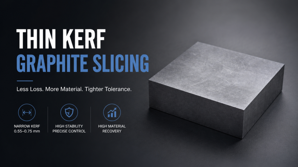
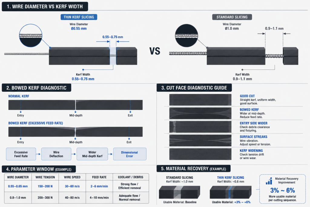
In standard graphite slicing, kerf width is determined primarily by wire diameter plus the abrasive layer, with some additional spread from process dynamics. Thin kerf graphite slicing changes this by using smaller-diameter wire — typically moving from 0.8–1.0 mm down to 0.5–0.7 mm — combined with adjusted tension, speed, and feed parameters to maintain wire stability at reduced diameter.
The direct result: less material lost per cut. On a block being sliced into 10 mm sections, reducing kerf from 1.0 mm to 0.6 mm recovers roughly 4% more usable material across the full cut sequence. On expensive isostatic graphite used in semiconductor applications, that 4% translates directly into production cost.
The indirect effect is less obvious: thinner wire is less rigid, more sensitive to lateral force, and more prone to path deviation under load. Thin kerf graphite slicing does not just mean installing smaller wire — it means rebuilding the process around a different balance between cutting efficiency and wire stability.
Process Parameters That Drive Thin Kerf Stability
Four parameters determine whether a thin kerf graphite slicing process holds stable across a full production run.
Wire Tension
Wire tension is the primary stability control in thin kerf graphite slicing. Lower-diameter wire has less cross-sectional stiffness, so tension must be calibrated more precisely than in standard slicing. Too low, and the wire deflects under lateral load from the graphite, producing a curved or tapered cut. Too high, and thin wire fatigue accelerates — wire breaks mid-batch are more common, and kerf variation increases near the break point.
For most fine-grain and isostatic graphite grades, thin kerf wire in the 0.5–0.7 mm range operates in a narrower tension window than standard wire. The exact range depends on wire construction and graphite hardness, but the practical consequence is that open-loop tension settings need more frequent verification during a run. A drift of 10–15 N in effective tension that would be acceptable with 1.0 mm wire can produce visible kerf variation with 0.55 mm wire.
Wire Speed
Higher wire speed improves material removal efficiency and surface finish in graphite, but the relationship is not linear for thin kerf slicing. Above a certain speed threshold, thin wire begins to vibrate longitudinally — a resonance effect driven by wire length, tension, and speed combination. When this happens, the effective kerf widens rather than narrows, directly defeating the purpose of using thin wire.
In practice, thin kerf graphite slicing typically runs at wire speeds similar to or slightly lower than standard slicing, rather than pushing higher. The speed advantage from thinner wire comes from feed rate flexibility, not from wire speed alone.
Feed Rate
Feed rate in thin kerf graphite slicing needs to account for two competing factors: cutting efficiency (which favors higher feed) and wire loading (which favors lower feed). Thin wire loaded beyond its capacity flexes and produces a bowed kerf — the center of the cut is wider than the entry and exit, which appears as a curved slice surface when the part is measured.
The bowed kerf problem is specific to thin kerf slicing and does not appear in the same way with standard wire. It shows up most clearly on deep cuts — long graphite blocks where the wire travels a significant distance under lateral load. The diagnostic: if kerf width measured at mid-depth is consistently wider than at entry, feed rate is too high for the wire diameter and block length combination.
Coolant Flow and Debris Management
Thin kerf cuts produce a narrower channel, which means debris clearance is more critical. In graphite dry cutting operations, dust extraction must be strong enough. For operations targeting kerf width reduction specifically, see the operational guidance in how to reduce kerf loss in graphite cutting to clear fine graphite particles from a narrower kerf — particles that re-enter the cut zone act as secondary abrasives and accelerate wire wear. In wet slicing, coolant flow needs to be matched to the reduced channel cross-section.
One failure mode that appears specifically in thin kerf graphite slicing: particle buildup at the wire entry point. On soft graphite grades, particles can compact at the wire entry and create a localized load spike that deflects the wire. The symptom is a curved entry zone on the cut face, with the rest of the surface appearing normal.
Thin Kerf Graphite Slicing vs Standard Slicing: Where the Difference Matters
| Parameter | Standard Slicing | Thin Kerf Slicing |
|---|---|---|
| Wire diameter | 0.8–1.0 mm | 0.5–0.7 mm |
| Kerf width | 0.9–1.1 mm | 0.55–0.75 mm |
| Tension sensitivity | Moderate | High — narrower operating window |
| Wire vibration risk | Low | Moderate — needs speed calibration |
| Bowed kerf risk | Low | Moderate to high on deep cuts |
| Material recovery | Baseline | 3–6% improvement per cut sequence |
| Applicable graphite grades | Most grades | Best on fine-grain and isostatic; difficult on coarse or porous grades |
| Batch yield consistency | Easier to hold | Requires tighter process control |
The material recovery advantage is consistent. The process control requirement is also consistent — thin kerf graphite slicing does not tolerate the same parameter variability that standard slicing can absorb.
Where Thin Kerf Graphite Slicing Breaks Down
Thin kerf slicing is not the right process in every situation. Three conditions reliably produce poor outcomes.
Coarse or porous graphite grades. Coarse-grain graphite has irregular fracture behavior at the cut zone. Thin wire interacts with these irregular zones through localized load spikes that deflect the wire path. The result is inconsistent kerf width and surface quality that is difficult to control even with conservative parameters. Standard slicing with appropriate wire diameter handles coarse grades more reliably. See SGL Carbon’s graphite grade documentation for grade-specific characteristics that affect sliceability.
Very long cuts at high depth. Wire sag increases with unsupported wire length. On deep graphite blocks — above roughly 200 mm in many configurations — thin wire sag under gravity and lateral load becomes significant enough to produce bowed cuts even at conservative feed rates. This is a geometry constraint, not a parameter problem. Increasing tension to compensate increases wire fatigue. The trade-off has a ceiling, and thin kerf slicing on very deep blocks often produces worse dimensional results than standard wire, not better.
Production environments without process monitoring. Thin kerf slicing is sensitive to variation in ways that accumulate invisibly. Tool wear, tension drift, and coolant changes that would produce minor kerf variation in standard slicing produce larger and faster kerf variation in thin kerf slicing. Operations without mid-batch dimensional sampling and tension verification tend to see batch yield collapse toward the end of a run. For the relationship between process monitoring and yield, see our discussion of graphite cutting yield improvement.
Parameter Diagnosis: Reading the Cut Face
The cut face of a graphite slice carries diagnostic information about which parameter was out of range.
Straight kerf, uniform width, good surface: Parameters are matched. Proceed.
Bowed kerf — wider at mid-depth than at entry/exit: Feed rate too high for the wire diameter and block length. Reduce feed rate, or switch to a slightly larger wire diameter.
Entry-side kerf wider than the rest of the cut: Wire entry loading issue — debris buildup or inconsistent fixturing. Check fixturing rigidity and debris clearance at wire entry.
Kerf width increasing progressively across a batch: Tool wear or tension drift. Check cumulative cutting time against wire replacement schedule and re-verify tension setting.
Surface streaks parallel to cutting direction: Wire vibration. Reduce wire speed or adjust tension to move out of resonance range.
This diagnostic approach assumes the process was stable at the start of the batch. If the very first cuts are out of specification, the issue is initial setup rather than drift. For detailed setup validation methodology, Toyo Tanso’s process documentation on graphite slicing covers grade-specific baseline parameter recommendations.
When to Use Thin Kerf Graphite Slicing
Strong fit:
- Fine-grain isostatic graphite in semiconductor, optical, or high-precision industrial applications
- High raw material cost where kerf recovery directly affects unit economics
- Moderate block depths (under 150–200 mm) where wire sag is manageable
- Operations with process monitoring in place (mid-batch sampling, tension verification)
Weak fit:
- Coarse-grain or porous graphite grades
- Deep blocks where wire sag at thin diameters exceeds dimensional tolerance
- High-volume continuous operations without systematic process control
Thin kerf slicing is a precision process. It delivers consistent results when deployed in conditions that match its constraints, and inconsistent results when those constraints are ignored. The starting point is always a first-article validation on the specific graphite grade and geometry — not an assumption that thin wire automatically produces better results than standard wire. For a complete view of kerf economics and material recovery, see low-kerf graphite cutting.
FAQ
What wire diameter defines “thin kerf” in graphite slicing?
There is no fixed boundary, but thin kerf graphite slicing generally refers to wire diameters below 0.7–0.75 mm, where process sensitivity and parameter requirements differ meaningfully from standard slicing with 0.8–1.0 mm wire. The distinction matters because the setup, monitoring, and acceptable parameter ranges are different enough to treat as a separate process category.
Why does my thin kerf cut produce a bowed surface on deep blocks?
Bowed kerf — wider at mid-depth than at the entry and exit faces — is caused by wire deflection under lateral load. Thin wire flexes more than standard wire under the same load, and on long cuts the deflection accumulates. Reducing feed rate is the first adjustment; if the problem persists, the block depth may exceed the practical range for the wire diameter in use.
Can I use thin kerf slicing on all graphite grades?
No. Coarse-grain and porous graphite grades produce irregular fracture behavior at the cut zone that causes localized wire loading and kerf variation. Thin kerf slicing is most effective on fine-grain and isostatic grades where the cut zone behavior is more uniform. The same wire and parameters that work well on isostatic graphite may produce poor results on coarser grades.
How do I know if my process is drifting mid-batch?
Measure kerf width and part dimensions at regular intervals — every 30–50 parts in most production settings. Plot the measurements against part number or time. Progressive widening of kerf or drift in part thickness indicates tension drift or tool wear. A sudden step change usually indicates a process event: wire replacement, tension adjustment, or coolant change.
Is thin kerf slicing always more cost-effective than standard slicing?
Not always. The material recovery advantage is real, but thin kerf slicing requires tighter process control, more frequent monitoring, and potentially higher wire consumption if parameters are not optimized. For low-value graphite grades where material recovery has limited economic impact, the process overhead may not justify the switch to thin wire.