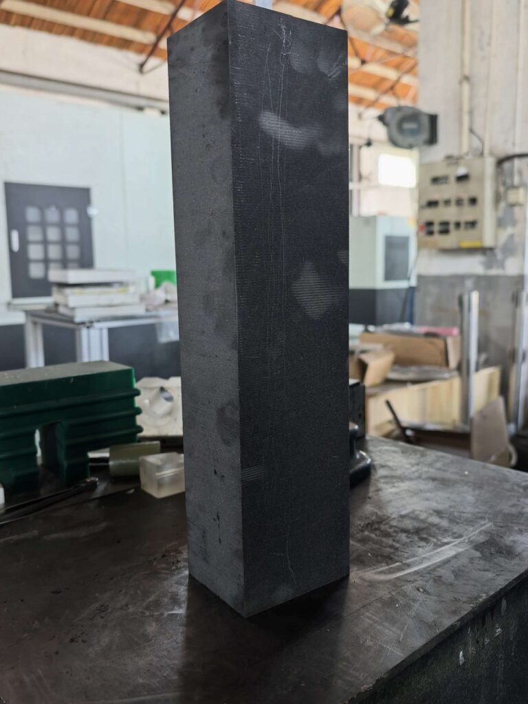
얇은 절단폭 흑연 슬라이싱은 표준 슬라이싱보다 더 좁은 절단 폭을 생성하여 블록당 더 많은 재료를 회수하면서 배치 전체에 걸쳐 더 엄격한 치수 공차를 유지합니다. 이 공정은 매개변수가 특정 흑연 등급 및 형상과 일치할 때 잘 작동합니다. 일치하지 않으면 와이어 편차, 표면 줄무늬 및 얇은 와이어를 사용함에도 불구하고 목표보다 넓게 벗어나는 절단폭과 같이 복구하기 어려운 빠른 실패 모드가 발생합니다.
이 페이지는 다음의 공정 특성을 다룹니다. 얇은 톱날 흑연 슬라이싱, 공정이 유지되는지 여부를 결정하는 매개변수 결정, 그리고 설정이 아무리 최적화되어 있어도 얇은 절단폭이 잘못된 선택인 상황.
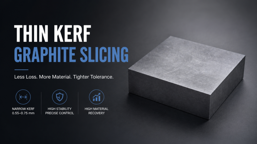
얇은 절단폭 흑연 슬라이싱이 실제로 변경하는 것
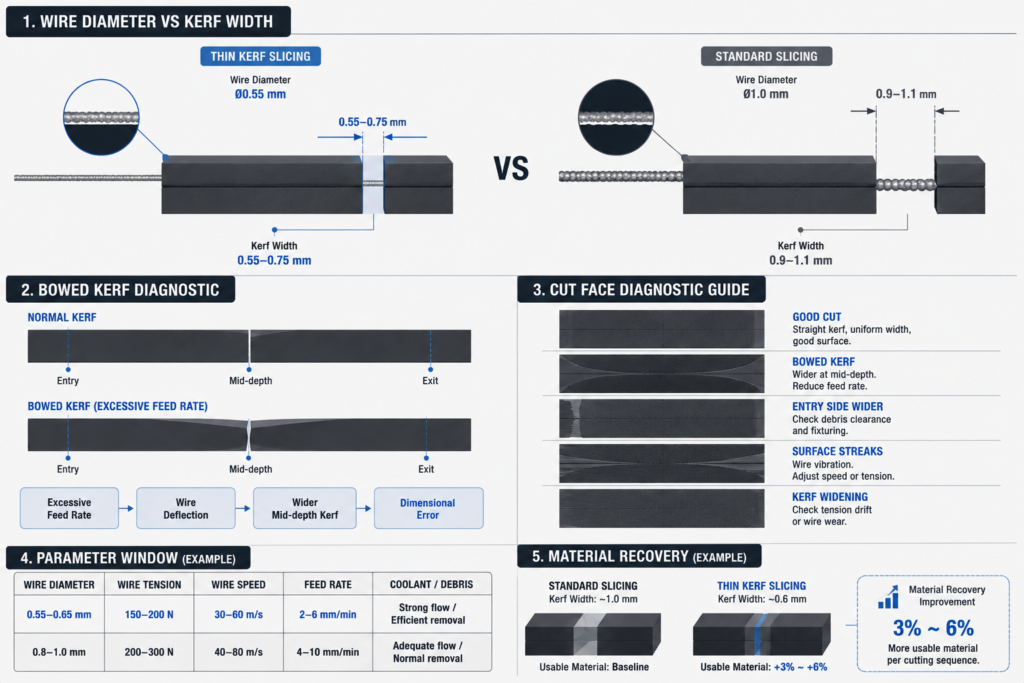
표준 흑연 슬라이싱에서 절단폭은 주로 와이어 직경과 연마재 층에 의해 결정되며, 공정 역학에 의해 약간의 추가 확산이 발생합니다. 얇은 절단폭 흑연 슬라이싱 이는 더 작은 직경의 와이어(일반적으로 0.8–1.0mm에서 0.5–0.7mm로 변경)를 사용하고 조정된 장력, 속도 및 공급 매개변수를 결합하여 감소된 직경에서 와이어 안정성을 유지함으로써 이를 변경합니다.
직접적인 결과: 절단당 손실되는 재료가 줄어듭니다. 10mm 섹션으로 슬라이싱되는 블록에서 절단폭을 1.0mm에서 0.6mm로 줄이면 전체 절단 시퀀스에서 약 41% 더 많은 사용 가능한 재료를 회수할 수 있습니다. 반도체 응용 분야에 사용되는 비싼 등방성 흑연의 경우, 이 41%는 생산 비용으로 직접 전환됩니다.
간접적인 효과는 덜 분명합니다. 더 얇은 와이어는 강성이 낮고 측면 힘에 더 민감하며 하중 하에서 경로 편차에 더 취약합니다. 얇은 절단폭 흑연 슬라이싱 단순히 더 작은 와이어를 설치하는 것을 의미하는 것이 아니라, 절단 효율성과 와이어 안정성 사이의 다른 균형을 중심으로 공정을 재구축하는 것을 의미합니다.
얇은 절단폭 안정성을 유도하는 공정 매개변수
네 가지 매개변수가 얇은 절단폭 흑연 슬라이싱 공정이 전체 생산 실행 동안 안정적으로 유지되는지 여부를 결정합니다.
와이어 장력
와이어 장력은 얇은 절단폭 흑연 슬라이싱의 주요 안정성 제어입니다. 더 작은 직경의 와이어는 단면 강성이 낮으므로 표준 슬라이싱보다 장력을 더 정확하게 보정해야 합니다. 너무 낮으면 와이어가 흑연의 측면 하중으로 인해 휘어져 구부러지거나 테이퍼진 절단을 생성합니다. 너무 높으면 얇은 와이어 피로가 가속화되어 배치 중간에 와이어가 끊어지는 경우가 더 많고 끊어지는 지점 근처에서 절단폭 변동이 증가합니다.
대부분의 미세 입자 및 등방성 흑연 등급의 경우, 0.5–0.7mm 범위의 얇은 절단폭 와이어는 표준 와이어보다 더 좁은 장력 창에서 작동합니다. 정확한 범위는 와이어 구조와 흑연 경도에 따라 다르지만, 실제 결과는 개방 루프 장력 설정이 실행 중에 더 자주 확인되어야 한다는 것입니다. 1.0mm 와이어로 허용되는 10–15N의 유효 장력 드리프트는 0.55mm 와이어로 눈에 보이는 절단폭 변동을 유발할 수 있습니다.
와이어 속도
더 높은 와이어 속도는 흑연의 재료 제거 효율성과 표면 마감을 향상시키지만, 얇은 절단폭 슬라이싱의 경우 이 관계는 선형적이지 않습니다. 특정 속도 임계값 이상에서는 얇은 와이어가 종 방향으로 진동하기 시작합니다. 이는 와이어 길이, 장력 및 속도 조합에 의해 구동되는 공명 효과입니다. 이 경우, 얇은 와이어 사용의 목적을 직접적으로 무효화하면서 유효 절단폭이 좁아지는 대신 넓어집니다.
실제로 얇은 절단폭 흑연 슬라이싱은 일반적으로 와이어 속도만으로는 속도 이점을 얻는 것이 아니라, 표준 슬라이싱보다 더 높게 밀어붙이는 대신 와이어 속도가 비슷하거나 약간 낮은 속도로 실행됩니다.
피드 속도
얇은 절단폭 흑연 슬라이싱의 공급 속도는 절단 효율성(공급 속도가 높을수록 좋음)과 와이어 부하(공급 속도가 낮을수록 좋음)라는 두 가지 상반된 요인을 고려해야 합니다. 용량을 초과하여 부하가 걸린 얇은 와이어는 휘어져 구부러진 절단폭을 생성합니다. 즉, 절단의 중심이 입구와 출구보다 넓으며, 부품을 측정할 때 구부러진 슬라이스 표면으로 나타납니다.
구부러진 절단폭 문제는 얇은 절단폭 슬라이싱에 특유하며 표준 와이어에서는 동일한 방식으로 나타나지 않습니다. 깊은 절단, 즉 와이어가 측면 하중 하에서 상당한 거리를 이동하는 긴 흑연 블록에서 가장 명확하게 나타납니다. 진단: 중간 깊이에서 측정된 절단폭이 입구보다 일관되게 넓으면 공급 속도가 와이어 직경 및 블록 길이 조합에 비해 너무 높습니다.
냉각수 흐름 및 파편 관리
얇은 절단폭 절단은 더 좁은 채널을 생성하므로 파편 제거가 더 중요합니다. 흑연 건식 절단 작업, 에서 먼지 추출은 충분히 강력해야 합니다. 절단폭 감소를 구체적으로 목표로 하는 작업의 경우, 다음의 운영 지침을 참조하십시오. 흑연 절단 시 커프 손실을 줄이는 방법 좁은 절단폭에서 미세 흑연 입자를 제거합니다. 입자가 절단 영역으로 다시 들어가면 2차 연마재 역할을 하여 와이어 마모를 가속화합니다. 습식 슬라이싱의 경우 냉각수 흐름을 감소된 채널 단면적에 맞춰야 합니다.
얇은 절단폭 흑연 슬라이싱에서 특히 나타나는 한 가지 실패 모드는 와이어 입구 지점에서의 입자 축적입니다. 부드러운 흑연 등급의 경우 입자가 와이어 입구에 압축되어 국부적인 하중 스파이크를 생성하여 와이어를 편향시킬 수 있습니다. 증상은 절단면의 구부러진 입구 영역이며 나머지 표면은 정상으로 보입니다.
얇은 절단폭 흑연 슬라이싱 대 표준 슬라이싱: 차이가 중요한 곳
| 매개변수 | 표준 슬라이싱 | 얇은 절단폭 슬라이싱 |
|---|---|---|
| 와이어 직경 | 8–1.0 mm | 5–0.7 mm |
| 커프 너비 | 9–1.1 mm | 55–0.75 mm |
| 장력 민감도 | 보통 | 높음 — 더 좁은 작동 창 |
| 와이어 진동 위험 | 낮은 | 보통 — 속도 보정 필요 |
| 구부러진 절단폭 위험 | 낮은 | 깊은 절단에서 보통에서 높음 |
| 재료 회수 | 기준선 | 절단 시퀀스당 3–6% 개선 |
| 적용 가능한 흑연 등급 | 대부분의 등급 | 미세 입자 및 등방성 등급에 가장 적합; 거친 또는 다공성 등급에는 어려움 |
| 배치 수율 일관성 | 유지하기 쉬움 | 더 엄격한 공정 제어 필요 |
재료 회수 이점은 일관됩니다. 공정 제어 요구 사항도 일관됩니다. 얇은 톱날 흑연 슬라이싱 표준 슬라이싱이 흡수할 수 있는 매개변수 변동성을 허용하지 않습니다.
Where Thin Kerf Graphite Slicing Breaks Down
Thin kerf slicing is not the right process in every situation. Three conditions reliably produce poor outcomes.
Coarse or porous graphite grades. Coarse-grain graphite has irregular fracture behavior at the cut zone. Thin wire interacts with these irregular zones through localized load spikes that deflect the wire path. The result is inconsistent kerf width and surface quality that is difficult to control even with conservative parameters. Standard slicing with appropriate wire diameter handles coarse grades more reliably. See SGL Carbon’s graphite grade documentation for grade-specific characteristics that affect sliceability.
Very long cuts at high depth. Wire sag increases with unsupported wire length. On deep graphite blocks — above roughly 200 mm in many configurations — thin wire sag under gravity and lateral load becomes significant enough to produce bowed cuts even at conservative feed rates. This is a geometry constraint, not a parameter problem. Increasing tension to compensate increases wire fatigue. The trade-off has a ceiling, and thin kerf slicing on very deep blocks often produces worse dimensional results than standard wire, not better.
Production environments without process monitoring. Thin kerf slicing is sensitive to variation in ways that accumulate invisibly. Tool wear, tension drift, and coolant changes that would produce minor kerf variation in standard slicing produce larger and faster kerf variation in thin kerf slicing. Operations without mid-batch dimensional sampling and tension verification tend to see batch yield collapse toward the end of a run. For the relationship between process monitoring and yield, see our discussion of 흑연 절단 수율 향상.
Parameter Diagnosis: Reading the Cut Face
The cut face of a graphite slice carries diagnostic information about which parameter was out of range.
Straight kerf, uniform width, good surface: Parameters are matched. Proceed.
Bowed kerf — wider at mid-depth than at entry/exit: Feed rate too high for the wire diameter and block length. Reduce feed rate, or switch to a slightly larger wire diameter.
Entry-side kerf wider than the rest of the cut: Wire entry loading issue — debris buildup or inconsistent fixturing. Check fixturing rigidity and debris clearance at wire entry.
Kerf width increasing progressively across a batch: Tool wear or tension drift. Check cumulative cutting time against wire replacement schedule and re-verify tension setting.
Surface streaks parallel to cutting direction: Wire vibration. Reduce wire speed or adjust tension to move out of resonance range.
This diagnostic approach assumes the process was stable at the start of the batch. If the very first cuts are out of specification, the issue is initial setup rather than drift. For detailed setup validation methodology, Toyo Tanso’s process documentation on graphite slicing covers grade-specific baseline parameter recommendations.
When to Use Thin Kerf Graphite Slicing
Strong fit:
- Fine-grain isostatic graphite in semiconductor, optical, or high-precision industrial applications
- High raw material cost where kerf recovery directly affects unit economics
- Moderate block depths (under 150–200 mm) where wire sag is manageable
- Operations with process monitoring in place (mid-batch sampling, tension verification)
Weak fit:
- Coarse-grain or porous graphite grades
- Deep blocks where wire sag at thin diameters exceeds dimensional tolerance
- High-volume continuous operations without systematic process control
Thin kerf slicing is a precision process. It delivers consistent results when deployed in conditions that match its constraints, and inconsistent results when those constraints are ignored. The starting point is always a first-article validation on the specific graphite grade and geometry — not an assumption that thin wire automatically produces better results than standard wire. For a complete view of kerf economics and material recovery, see low-kerf graphite cutting.
자주 묻는 질문
What wire diameter defines “thin kerf” in graphite slicing?
There is no fixed boundary, but thin kerf graphite slicing generally refers to wire diameters below 0.7–0.75 mm, where process sensitivity and parameter requirements differ meaningfully from standard slicing with 0.8–1.0 mm wire. The distinction matters because the setup, monitoring, and acceptable parameter ranges are different enough to treat as a separate process category.
Why does my thin kerf cut produce a bowed surface on deep blocks?
Bowed kerf — wider at mid-depth than at the entry and exit faces — is caused by wire deflection under lateral load. Thin wire flexes more than standard wire under the same load, and on long cuts the deflection accumulates. Reducing feed rate is the first adjustment; if the problem persists, the block depth may exceed the practical range for the wire diameter in use.
Can I use thin kerf slicing on all graphite grades?
No. Coarse-grain and porous graphite grades produce irregular fracture behavior at the cut zone that causes localized wire loading and kerf variation. Thin kerf slicing is most effective on fine-grain and isostatic grades where the cut zone behavior is more uniform. The same wire and parameters that work well on isostatic graphite may produce poor results on coarser grades.
How do I know if my process is drifting mid-batch?
Measure kerf width and part dimensions at regular intervals — every 30–50 parts in most production settings. Plot the measurements against part number or time. Progressive widening of kerf or drift in part thickness indicates tension drift or tool wear. A sudden step change usually indicates a process event: wire replacement, tension adjustment, or coolant change.
Is thin kerf slicing always more cost-effective than standard slicing?
Not always. The material recovery advantage is real, but thin kerf slicing requires tighter process control, more frequent monitoring, and potentially higher wire consumption if parameters are not optimized. For low-value graphite grades where material recovery has limited economic impact, the process overhead may not justify the switch to thin wire.