
You can slice graphite all day long, but if the thickness varies by 0.3 mm from one plate to the next — or worse, across a single plate — your downstream process pays the price. Grinding takes longer, material gets wasted, and reject rates climb.
Graphite slicing thickness control is the single most important quality metric in plate production. Get it right, and you ship plates that go straight into assembly with minimal finishing. Get it wrong, and every plate needs extra grinding to hit spec — eating into your margins and your lead time.
Why Graphite Slicing Thickness Control Matters
The Cost of Poor Thickness Control
When a graphite plate comes off the wire saw at 5.2 mm instead of 5.0 mm, that extra 0.2 mm has to be ground away. On a 200 × 100 mm plate, that’s approximately 2.5 cm³ of wasted graphite. At $50–$200/kg for isostatic grades, the material cost adds up fast across hundreds of plates.
But material waste isn’t the biggest cost. It’s the grinding time. Double-sided lapping or surface grinding runs at fixed removal rates. An extra 0.2 mm per plate might add 30–60 seconds of grinding time per piece. Over a production run of 1,000 plates, that’s 8–16 hours of additional machine time — directly reducing your output capacity.
Typical Tolerance Requirements
| 応用 | Thickness Tolerance | なぜ |
|---|---|---|
| Fuel cell bipolar plates | ±0.05 mm | Stack compression uniformity |
| EDM電極ブランク | ±0.1 mm | Consistent spark gap |
| Semiconductor wafer chucks | ±0.02 mm | Wafer flatness transfer |
| Heat spreaders | ±0.1 mm | Thermal interface contact |
| Heating elements | ±0.15 mm | Resistance consistency |
The tighter the tolerance, the more critical your graphite slicing thickness control becomes — and the less room you have for process variation.
What Causes Thickness Variation in Graphite Slicing
Understanding the sources of variation is the first step to controlling them. There are five primary causes:
1. Wire Deflection During Cutting
This is the most common cause of thickness variation. As the diamond wire cuts through the graphite block, cutting forces push the wire sideways. The wire bows in the middle of the cut, producing a plate that’s thinner at the center than at the edges.
Wire deflection increases with:
- Higher feed rate (more cutting force)
- Lower wire tension (less resistance to deflection)
- Longer cut length (more wire span to bow)
- Worn diamond coating (higher friction)
A plate cut from a 200 mm wide block will show more center-to-edge variation than one cut from a 50 mm block — simply because the wire has more length to deflect.
2. Block Fixturing Problems
If the graphite block moves during cutting — even 0.05 mm — that movement transfers directly into the plate thickness. Common fixturing issues:
- Insufficient clamping force. Graphite is porous and doesn’t grip as well as metal. Standard vise clamping may not hold under cutting forces.
- Adhesive bond failure. When blocks are glued to the work table, incomplete adhesive coverage or weak bond strength allows micro-movement.
- Thermal expansion. The block and fixture expand at different rates during extended cutting. Without compensation, this introduces progressive thickness drift across a batch.
3. Wire Wear and Degradation
Diamond wire doesn’t cut at constant efficiency. As the diamond abrasive wears, cutting force increases for the same feed rate. This causes:
- Gradually increasing wire deflection over the wire’s service life
- First plates in a batch cut slightly differently from the last plates
- Sudden changes in cutting behavior when heavily worn sections of wire enter the cut zone
Monitoring wire condition and replacing wire at consistent intervals — not when it breaks — is essential for graphite slicing thickness control across large batches.
4. Graphite Density Variation
Graphite blocks are not perfectly homogeneous. Even isostatic-pressed graphite from manufacturers like SGL Carbon has density variations of 1–3% within a single block. Higher density zones resist cutting, causing the wire to deflect more. Lower density zones cut faster, potentially causing the wire to advance too quickly.
The result is thickness variation that follows the density pattern of the block — something you can’t control, only compensate for.
熱的影響
ワイヤーとグラファイトの間の摩擦は熱を発生させます。この熱は以下を引き起こします:
- ワイヤーの熱膨張(有効張力を変化させる)
- ブロックの熱膨張(カット位置を変化させる)
- クーラント粘度の変化(潤滑に影響する)
これらの熱的影響は、カット中に累積します。大きなブロックを30分かけてカットすると、小さなブロックを5分かけてカットするよりも熱ドリフトが大きくなります。.
グラファイトスライシングの厚さ制御を改善する方法
ワイヤー張力の最適化
ワイヤー張力は、グラファイトスライシングの厚さ制御において最も効果的な手段です。張力を高くするとワイヤーのたわみが減少し、より一貫したプレートの厚さが得られます。しかし、限界があります。高すぎるとワイヤーが破損したり、早期に疲労したりします。.
最適なアプローチは サーボ制御された張力 カット全体で一定の力を維持します。これにより、ワイヤーの伸び、熱膨張、スプール径の変化が自動的に補正されます。手動での張力調整では、この一貫性には及びません。.
適応型フィード制御の使用
固定された送り速度で実行する代わりに、適応型制御はリアルタイムの切削抵抗に基づいて送り速度を調整します。
| 一般的な結果 | 適応型応答 | 厚さの利点 |
|---|---|---|
| ワイヤーがより密度の高いゾーンに入る | 送り速度を低下させる | ワイヤーのたわみが少なくなる |
| ワイヤーがより柔らかいゾーンに入る | 送り速度を増加させる | ワイヤーの蛇行を防ぐ |
| ワイヤーがカットの終わりに近づく | 送りを遅くする | よりクリーンな出口、チップの発生が少ない |
| クーラントの流れが低下する | 送りを一時停止する | 熱による損傷を防ぐ |
これは、グラファイトの内部密度が変化するため、特に重要です。密度が2%変化するブロックを固定送り速度でカットすると、測定可能な厚さの違いが生じます。適応型制御はこれを最小限に抑えます。.
クーラント供給の制御
一貫したクーラントの流れは、破片を洗い流す以上のことを行います。それは:
- カットゾーンの温度を安定させる
- 一貫した潤滑を提供する(切削力に影響する)
- 長時間のカット中の熱ドリフトを防ぐ
グラファイトスライシングの厚さ制御では、クーラントの流量と温度を監視し、一定に保つ必要があります。クーラントシステムが再循環する場合、生産シフト中にクーラント温度が±2°Cを超えて変動しないことを確認してください。.
統計的プロセス制御の実装
すべてのプレートを測定するだけでは不十分です。傾向を追跡する必要があります。
- プレートごとに3〜5点(中央、4つの端)で厚さを測定する
- カットシーケンスごとに値を記録する
- バッチ実行中の傾向をプロットする
- 管理限界を設定する(例:目標値から±0.05 mm)
- 傾向が管理限界に近づいたら、是正措置を講じる(ワイヤー交換、張力調整、クーラントチェック)
これにより、仕様外のプレートが発生する前に、徐々にドリフトを検出できます。反応的な検査(バッチ完了後に測定)は不良品を見つけますが、それを防ぐことはできません。手動検査中のグラファイト粉塵への曝露も、以下に準拠する必要があります。 OSHAの許容曝露限界.
ワイヤー径をプレート厚さに合わせる
よくある間違いは、すべての作業に同じワイヤーを使用することです。薄いプレート( 10 mm)には、より太いワイヤー(0.5〜0.65 mm)を使用します。ワイヤー径は剛性に影響します。太いワイヤーはたわみが少ないですが、より広いカーフ(切り溝)を切断します。.
目標は、ワイヤー剛性が必要なものに対して十分であるバランス点を見つけることです graphite slicing thickness control 過度なことなく kerf loss.
グラファイトスライシングの厚さ制御の測定
推奨される測定方法
| Measurement | ツール | Resolution |
|---|---|---|
| プレート厚さ(一点) | デジタルマイクロメータ | 0.001 mm |
| 厚さマップ(複数点) | XYステージ付きCMMまたは厚さゲージ | 0.001 mm |
| TTV(総厚さ変動) | 全面自動ゲージ | 0.001 mm |
| インプロセスモニタリング | レーザー変位センサー | 0.01 mm |
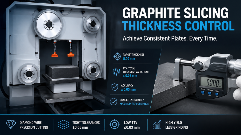
TTV (総厚さ変動)は、グラファイトスライシングの厚さ制御において最も意味のある単一の数値です。これは、単一プレートの最も厚い点と最も薄い点の最大の違いを捉えます。TTVが0.03 mmであれば優れており、0.1 mmであればほとんどの用途で許容範囲内ですが、0.2 mmを超える場合はプロセス上の問題を示します。.
厚さ制御とプロセス全体との接続
グラファイトスライシングの厚さ制御は孤立して存在するものではありません。それは直接以下に接続されています。
- スライシングプロセス — 切断パラメータが初期の厚さ精度を決定します
- Flatness and parallelism — プレートは平均して目標厚さに達する可能性がありますが、それでもくさび形である可能性があります
- 欠陥 — 端部の欠けは、プレート端部での使用可能な厚さを効果的に減少させます
- カーフ損失 — より広いカーフは、切断計画における誤差の余地を少なくすることを意味します
これらの品質要因がすべてどのように連携するかについての概要については、当社の 精密グラファイトスライス pillar guide.


