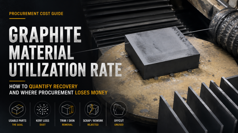
The EDM graphite electrode cutting challenges we see in production are not edge cases. They are systematic problems that appear in every high-precision electrode line, and they compound across batch sizes. Edge chipping wastes material at slice 1. Dimensional drift wastes it at slice 200. Internal stress waits three weeks and then wastes an entire mold.
Here’s what actually goes wrong at the cutting stage, in the order most shops discover them the hard way.
What Are the Main EDM Graphite Electrode Cutting Challenges?
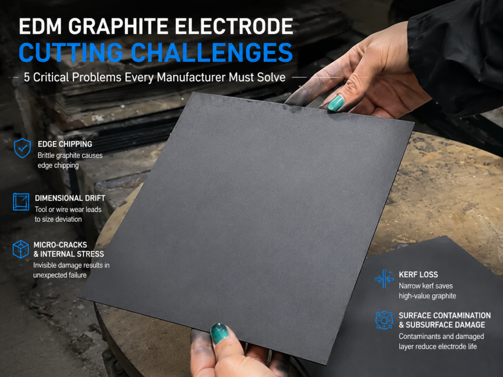
The five core EDM graphite electrode cutting challenges are:
- Edge integrity and chipping risk — brittle graphite fractures at slice entry and exit
- Dimensional drift in batch production — tool wear or wire wear silently shifts geometry across a run
- Internal stress and micro-cracking — invisible damage that surfaces mid-EDM
- Kerf loss in high-value electrodes — every millimeter of waste amplifies at $150/kg graphite
- Surface contamination and subsurface damage — cut face defects that polishing cannot rescue
None of these are cosmetic. Each one costs money at a different point in the production timeline — and each one has to be addressed at the cutting stage, because downstream operations cannot fully recover the loss.
Challenge 1: Edge Integrity and Chipping Risk
Graphite is brittle. The fracture toughness of isostatic fine-grain graphite is roughly 1.0–1.4 MPa·m^0.5, an order of magnitude below common tool steels. That means every point of mechanical contact between a cutting tool and the workpiece is a candidate crack initiation site.
You see this most clearly at slice entry and slice exit. A CNC tool bites into the surface — micro-fracture spreads outward from that first contact point. On exit, when the tool breaks through the far face, the unsupported material tears rather than shears cleanly.
The visual result is edge chipping: small conchoidal fractures along the perimeter of the cut face. On a precision electrode with a 45° chamfer or a fine internal feature, chipping isn’t a cosmetic problem. It changes the discharge geometry directly and reduces the effective electrode surface area at the exact points where EDM performance matters most.
Wire cutting reduces this because it doesn’t concentrate force at a single point. But even with wire cutting, if wire tension is wrong or feed rate is too aggressive, you’ll see the same graphite slicing defects — micro-chipping along the leading edge, tear-out at exit.
Field indicator: If more than 2% of your batch requires edge rework before it can move to shaping, edge integrity is your dominant cutting challenge.
Challenge 2: Dimensional Drift in Batch Production
This is the challenge that hits shops running long production runs. Piece 1 hits ±0.02 mm on the drawing. Piece 50 is still fine. By piece 150, you’re finding parts at 0.06 mm over. By 200, half the batch is out of spec.
The cause depends on your process:
- CNC machining: tool wear. Carbide and diamond-coated tools lose edge geometry monotonically. Compensation loops help but never fully eliminate drift.
- ダイヤモンドワイヤー切断: diamond loss from the wire abrasive surface, plus wire diameter reduction from wear. On long runs, both effects push cut geometry outward.
- Both processes: thermal drift in the machine frame, spindle bearing wear, coolant temperature variation.
The problem is that dimensional drift is often invisible until you do a mid-batch measurement audit — and most shops don’t. This is why the difference between graphite electrode cutting vs machining matters so much for high-volume electrode production: the two processes have fundamentally different drift curves, and choosing the wrong one for your batch size can quietly cost you 15–25% yield.
Field indicator: measure piece 1, piece 25, piece 50, piece 100 of any production run. If the four values drift monotonically in one direction, you have a drift problem — not random variation.
Challenge 3: Internal Stress and Micro-Cracking
This is the most dangerous of the EDM graphite electrode cutting challenges because you cannot see it during QC inspection. The electrode looks perfect. Dimensions are in spec. Surface finish is acceptable. And then two weeks into an EDM run, the electrode fractures under thermal cycling.
Cutting introduces internal stress in two ways:
- Mechanical: any contact force between tool and workpiece transfers residual stress into the surrounding grain structure
- Thermal: local heating at the cut face creates a temperature gradient into the bulk material; graphite’s low thermal conductivity in certain grades (especially fine-grain isostatic types documented by Toyo Tanso) traps this gradient long enough to cause micro-crack initiation
The result is a subsurface damage layer, typically 20–100 µm deep, filled with micro-cracks that are too small to detect without cross-sectional metallography. Under EDM thermal cycling — repeated heating and cooling during discharge — those micro-cracks propagate. Eventually one reaches the surface and the electrode fails.
To reduce this you have to control both the cutting force and the local heat load. That’s why graphite slicing stress management is a first-order design parameter, not an afterthought. Coolant flow rate, wire speed, feed rate — each affects how much energy is dumped into the workpiece per unit cut area.
Field indicator: if electrodes are failing after ~30–70% of expected service life, and the failure surface shows crack propagation from below the electrode surface rather than from a discharge point, internal stress is the root cause.
Challenge 4: Kerf Loss in High-Value Electrodes
Kerf loss is the material lost to the cut itself — the width of the slot the cutting method takes out. It doesn’t sound expensive until you do the math on premium graphite:
| Grade | Approximate material cost basis | Kerf loss sensitivity |
|---|---|---|
| Standard EDM graphite | 低い | 中程度 |
| Fine-grain isostatic | Mid | 高い |
| Ultra-fine-grain, high-purity (per SGL Carbon specifications) | プレミアム | Very high |
A CNC endmill has an effective kerf equivalent to its cut width plus finishing allowance — routinely 3–6 mm on a rough pass. A diamond wire saw operates at 0.3–0.6 mm kerf. On a 100 mm × 100 mm × 50 mm billet cut into ten electrodes, that difference is not marginal. It’s several hundred grams of premium graphite either used or wasted.
For high-value grades, kerf loss becomes the dominant material cost lever. Every percentage point of kerf reduction is amplified by the raw material cost, and on premium isostatic grades the amplification is significant. This is why グラファイトスライシングカーフ損失 is treated as a per-batch KPI in high-volume electrode shops, not just a spec sheet number.
Field indicator: divide the weight of your finished electrodes by the weight of the raw billet. If material yield is below 55–60% on premium grades, kerf loss is likely your largest single cost leakage.
Challenge 5: Surface Contamination and Subsurface Damage
The last of the major EDM graphite electrode cutting challenges is the cut face itself. Two failure modes:
Contamination: cutting chips embed into the porous graphite surface. Coolant residue oxidizes at the cut face. Iron particles from steel fixturing get pressed into softer grades. Any of these contaminants change the electrical resistance at the electrode surface — and in EDM, that translates directly to discharge instability.
Subsurface damage layer: below the visible surface, there is typically 20–80 µm of grain disruption from the cutting process. Grains fractured, bonding weakened, porosity increased. Polishing removes the top few microns but cannot rescue the damaged layer beneath.
This is why “we’ll polish it out later” is not a solution. Polishing removes material — it doesn’t heal it. If the subsurface damage extends 60 µm and you polish 20 µm, you have exposed damaged material to the discharge environment. That electrode will wear faster, spark less predictably, and fail earlier than one cut cleanly to begin with.
The manufacturing lesson: surface state at the cutting stage largely determines electrode service life. Downstream operations optimize what cutting produces — they cannot substitute for it.
How to Address These EDM Graphite Electrode Cutting Challenges
None of these five EDM graphite electrode cutting challenges have a single-parameter fix. Each one comes from a combination of process choice, tooling, and setup discipline. But the pattern of the fix is consistent across all five:
- Choose the cutting method that matches your material and batch size — for brittle, high-value graphite in medium-to-large batches, wire cutting resolves most of the mechanisms above at the physics level
- Set parameters conservatively during ramp-up — feed rate, wire speed, and coolant flow interact; lock down safe values before optimizing for throughput
- Measure mid-batch, not just at start and end — dimensional drift and edge integrity degrade continuously; sampling only piece 1 and piece 200 misses the transition zone
- Instrument for the invisible failures — cross-sectional inspection on 1–2 pieces per batch reveals internal stress and subsurface damage that visual QC misses
For a full comparison of how cutting method choice affects each of these five challenges, see our graphite electrode cutting vs machining breakdown.
If you’re evaluating a new electrode cutting process — or trying to diagnose which of these five challenges is dominant in your current line — get in touch. We’ll review your material grade, batch profile, and dimensional targets, and identify the cutting parameters most likely to solve the problem you’re actually facing.