A graphite profile cutting process starts with an access question: can the selected wire system reach the required contour while the retained part stays supported? A drawing that looks straightforward in plan view may contain an internal opening, blind feature or release condition that changes the route completely.
Define the output as a cut blank or a finished component before requesting a cycle-time estimate. Those are different jobs. A through-contour blank can still need holes, grooves, datum preparation or surface finishing.
Сайт graphite profile cutting topic page explains the broader application. This article follows the graphite profile cutting process from the drawing revision to the inspection record, without assuming that every contour is feasible on every machine.

Define the Graphite Profile Cutting Process Output
Separate incoming stock dimensions, cut geometry and final drawing requirements. Mark which surfaces the wire is expected to produce and which features belong to later operations. Include the stock allowance wherever the cut surface is not the finished surface.
Use a controlled drawing revision. If the supplier reviews one outline while production receives another corner radius, the original feasibility assessment may no longer apply. Keep the geometry file, drawing and quotation linked by revision.
Identify the material grade rather than describing the workpiece only as fine graphite. SGL Carbon distinguishes isostatic grades by their properties. The practical requirement here is material identification: a trial should use stock representative of the intended order.
Also identify the intended datum faces. An outline positioned correctly relative to the stock edge may still be incorrectly positioned relative to the final component datum. The inspection plan should make that distinction explicit.
Check External and Internal Access Separately
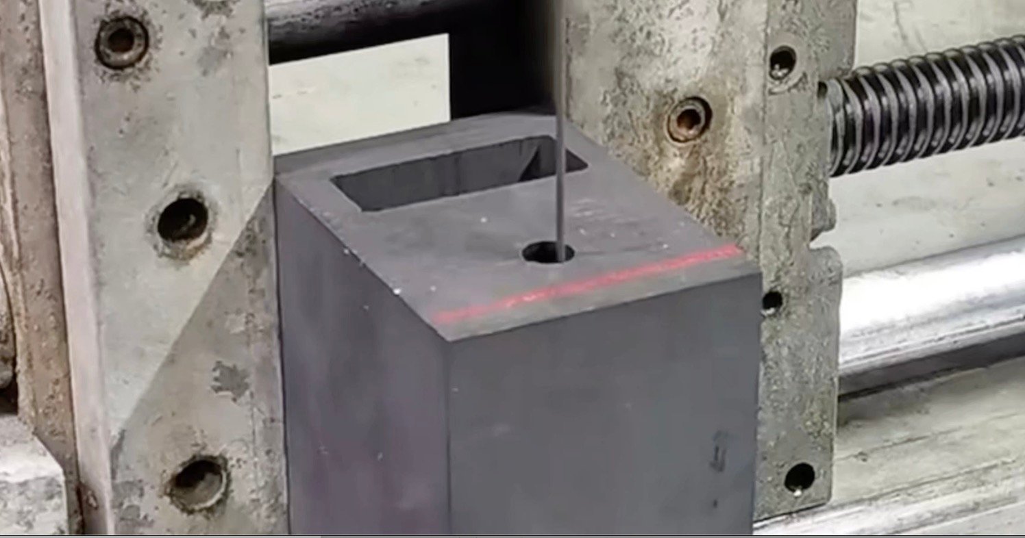
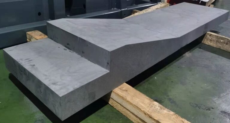
For an external contour, show where the wire enters, where it exits and how the offcut separates. Confirm clearance around the fixture and the orientation of the retained part. A path that is reachable at the start may be obstructed later by a support or loose offcut.
For a closed internal contour, obtain confirmation of the entry and threading arrangement from the equipment supplier. An endless loop does not automatically pass through every pre-existing opening. The actual wire system, joining method where applicable, machine configuration and stock geometry determine feasibility.
Do not use a generic outer-profile photograph to promise an internal feature. Equally, do not infer blind-pocket or arbitrary three-dimensional capability from the phrase CNC wire saw. Specify the requested feature and ask how it will be produced.
Review the outer-profile equipment и inner-profile equipment as separate starting points. Their existence is not a substitute for drawing-based confirmation.
Preserve Support Through the Cut Sequence
Mark the retained part and scrap region before planning the final separating pass. Determine what restrains both regions when the remaining material connection becomes small. Support must remain effective without obstructing the wire or damaging a surface reserved for finishing.
Avoid describing a thin bridge as safe merely because it survived a previous sample. Its geometry, material and loading conditions matter. Treat the bridge as a feature to evaluate, not as a universal fixture solution.
Plan the order of internal and external contours with the access and support requirements together. There is no universal rule that every internal feature must always be cut first; the selected route must preserve the references and restraint needed by subsequent passes.
A useful graphite profile cutting process sheet includes a simple sequence sketch. Number the passes and identify where the fixture changes. This is easier to review than a path file with no explanation of the physical setup.
Qualify the Graphite Profile Cutting Process Settings
Record wire type and condition, speed, tension, feed, relevant compensation and the program revision. Parameter names and units should match the machine documentation. A setting copied from a block-division test is not a qualified contour setting.
Pay attention to transitions and small features during the sample. Compare what happens on straight sections with the behavior near corners, entry, exit and unsupported regions. If the sample is measured only across its outside rectangle, those local differences may disappear from the report.
When changing a condition, identify what the test is intended to resolve. Compare samples with a controlled difference where practical. Do not attribute an improvement to path compensation if the fixture, material and wire were changed at the same time.
Keep a record of operator interventions. An accepted sample that required unrecorded manual corrections cannot be reproduced from the nominal program alone. It’s the actual process that needs qualifying, not just the file name.
Build the Inspection Plan Around the Contour
Agree how measured geometry will be aligned to the drawing. A free best-fit alignment and a datum-based evaluation can answer different questions. Use the alignment required by the component specification and report it alongside the result.
| Характеристика | Suggested review | Record to retain |
|---|---|---|
| Straight and curved outline | Compare the actual contour with the specified geometry | Measurement coverage and alignment |
| Внутреннее отверстие | Evaluate access-critical and functional regions | Opening identification and local deviations |
| Corner or narrow region | Inspect local form and edge damage | Position-marked observations |
| Through-thickness geometry | Compare relevant sections or faces | Sampling method and face identity |
| Finishing stock | Check the material reserved for later work | Allowance remaining by critical surface |
NIST’s measurement-process guidance covers repeatability and stability. Apply that principle by checking whether the inspection setup gives consistent results before interpreting a small difference as a cutting change.
For the distinction between size, geometry and acceptance conditions, use the руководство по высокоточной резке графита. Keep this article’s inspection plan specific to contour production.
Video: Graphite slicing and internal contours
Watch on YouTube · Vimfun Endless Diamond Wire Saw
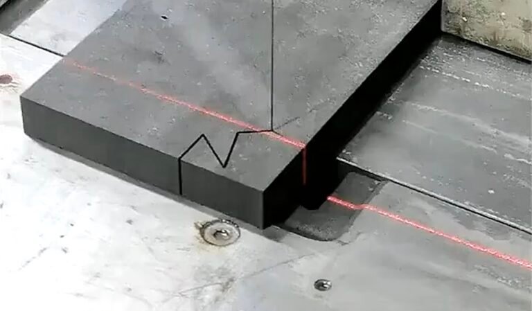
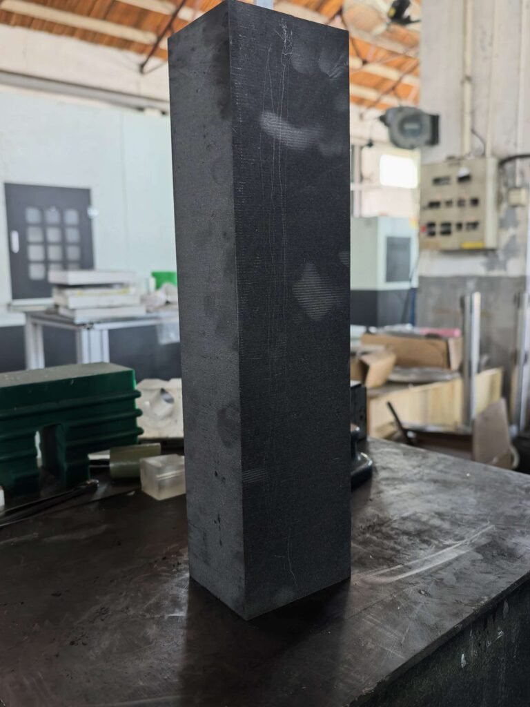
This process montage includes an upright block and an internal contour in round stock. Access, threading and acceptance requirements must still be checked for the actual drawing.
Field Notes: What the Available Test Does and Does Not Prove
The available SVI250-80 graphite bar record is a straight-sided blank trial, not a profile qualification. It used 0.8 mm wire and 42 mm/min feed on one nominal 500 × 87 × 70 mm bar with compensation off.
Its width increased from 87.00 to 87.30 mm along the sample. That documented shortcoming is relevant as an inspection warning: one successful dimension does not establish the whole geometry. It does not establish a contour radius, internal-opening capability or a profile-cutting feed range.
For a new graphite profile cutting process, the corresponding field evidence must come from a representative contour. Include its difficult feature, datum definition, fixture and measurements. Until that evidence exists, use the block record only for the limited metrology lesson it actually supports.
Decide What Must Be Finished After Cutting
List the features that remain after the contour is separated. A blind recess, threaded hole or specified finished surface may still require another machine. Reserve locating surfaces and stock for those operations when laying out the contour.
Choose wire cutting where it can produce a useful accessible blank, and use machining where the feature or final requirement calls for it. Compare that sequence with the alternative of machining the complete shape from larger stock.
The relevant comparison includes setup, consumables, inspection, accepted pieces and downstream work. It is not simply wire feed against spindle feed. The graphite machining alternatives page provides the wider route comparison.
Before releasing a batch, confirm that the finishing team accepts the blank definition. A contour can look correct in a photograph while leaving too little stock at one critical corner to produce the finished part.
Known Limitations / Trade-offs
A graphite profile cutting process qualified for one accessible external contour does not automatically qualify a closed internal opening. Stock thickness, local geometry, support and the wire arrangement may change the result or prevent the route entirely.
Extra support and retained bridges can preserve control but add removal or finishing work. A more generous allowance can reduce blank rejection while consuming material and machining time. Resolve those trade-offs against the finished drawing.
No universal minimum radius, maximum unsupported feature or guaranteed profile tolerance is established by this workflow. Those figures require equipment-specific data and representative testing. The absence of a measured limit should lead to an explicit qualification question, not an invented capability statement.
Prepare the Sample Handover
Label the sample with its orientation and drawing revision before it leaves the cutting area. Attach the critical-feature map and identify which surfaces remain unfinished. The receiving inspector should not have to infer the evaluation direction from a photograph. Keep any provisional acceptance condition visible until the required finishing and final checks are complete.
Questions for the Drawing Review
Is a CAD outline enough to start?
It can start the discussion, but provide material grade, stock dimensions and thickness, datums, final tolerances and the surfaces that will be finished later. The contour file alone usually does not describe the complete manufacturing requirement.
Should I ask for the smallest feature in the first trial?
Include the features that determine feasibility, together with representative support and thickness. A tiny isolated coupon may omit the restraint or access problem found on the real part. Agree a manageable sample that preserves those conditions.
Can an accepted sample become the production program?
Only after the actual setup, conditions, inspection and any interventions have been documented. Review repeated locating and wire condition when the order requires multiple parts. Keep the graphite profile cutting process linked to the drawing revision and accepted sample record.
Send your drawing through our profile-cutting enquiry page. Mark the internal openings, local radii and final-machining surfaces so the review can address the real part.