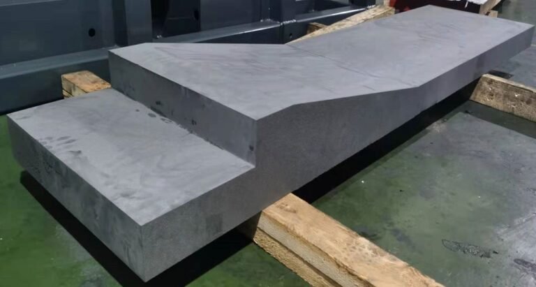
Choose between graphite block cutting vs slicing by defining the next usable output. If the job needs smaller stock sections, begin with division; if it needs repeated plates, qualify a slicing route. A shaped through-contour adds a different access and inspection problem.
These operations can belong to the same manufacturing chain. Treating them as competing names for one machine capability makes quotations difficult to compare and can leave the critical finishing operation out of the route.
This guide compares the output, setup and acceptance evidence for each operation. For the parent stock-preparation topic, see Découpe de blocs de graphite industriel.
Graphite Block Cutting vs Slicing Starts with the Output
Block division converts incoming stock into manageable blanks, bars or sections. The acceptance question is whether the new blank contains the required geometry and allowance and can be located for its next operation.
Slicing produces plates from stock with a specified thickness and face relationship. Plate count, thickness variation, edge condition and handling become part of the production requirement. A section that is suitable for rough blank preparation may need further work before it can be sliced as intended.
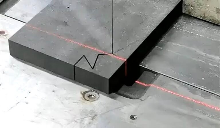
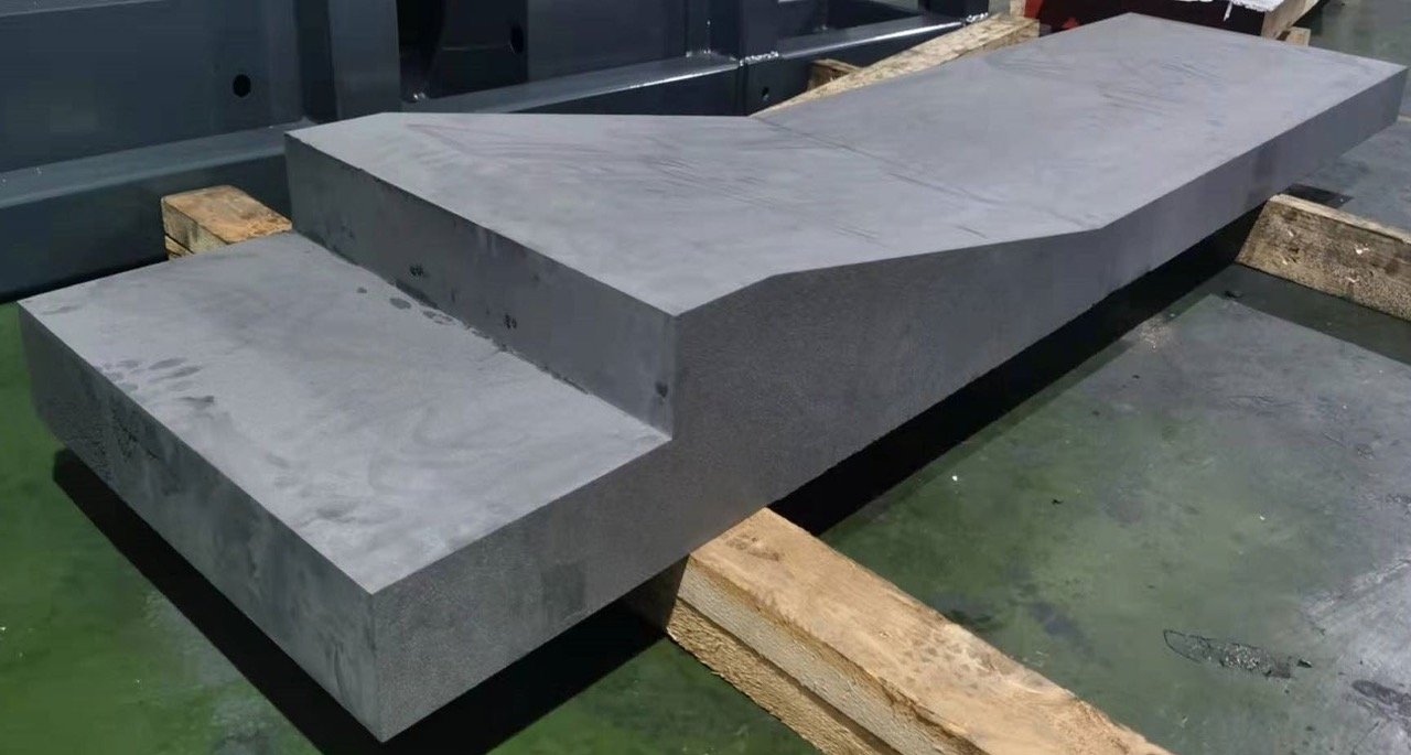
Profile cutting follows an outline rather than merely producing a smaller rectangular envelope. The route must address wire access, local geometry, retained-part support and how the measured contour relates to the drawing.
Material identity remains relevant across all three. SGL Carbon supplies different isostatic grades with distinct properties. Preserve the grade and lot information as the stock moves between operations, rather than applying one generic graphite recipe.
Compare Graphite Block Cutting vs Slicing and Profiling on Equal Terms
Use the same finished requirement when comparing graphite block cutting vs slicing and profiling. If one quotation ends with a rough blank while another includes inspection and finishing, their cycle times and prices describe different deliverables.
| Requirement | Division des blocs | Découpe | Profile cutting |
|---|---|---|---|
| Main output | Smaller stock section or blank | Plate or repeated plates | Accessible cut contour |
| Key reference | Seating face and cut-face relationships | Thickness reference and face geometry | Drawing datums and contour alignment |
| Main handling question | Support before and after separation | Support and removal of plates | Restraint of retained part and offcut |
| Inspection emphasis | Size, geometry and finishing stock | Thickness, face relationship and damage | Local outline and feature position |
| Typical next step | More cutting or machining | Profile cutting or finishing | Holes, datums or finishing as required |
The table is a process-selection aid, not a capability chart for every machine. Equipment travel, loading arrangement and accessible features need separate confirmation.
When Block Division Is the Useful First Operation
Choose division when the incoming block is larger than the stock required by the next step. Plan the cuts around the usable blanks, fixture access and the available material, not simply the maximum number of rectangles that fit in a drawing.
Mark any surfaces needed as datums. Repositioning after an initial cut changes the locating chain, and an offcut that appears usable may lack a suitable face for the following operation. Establish that face in the route or allow stock for doing so later.
Include loading and unloading in the review. A short cutting cycle does not establish a practical process if the separated piece cannot be restrained or removed using the approved handling arrangement.
For graphite block cutting vs slicing, division is often the upstream preparation question: what stock section will the slicing operation actually receive? Agree that section with the slicing team before cutting away its locating allowance.
When Slicing Should Define the Route
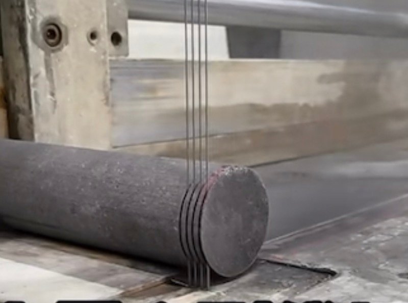
Choose a slicing-led route when repeated plates are the required output. Specify plate thickness, thickness variation, face relationships, required quantity and the surfaces that will be finished later.
Define whether the quoted thickness is as-cut or after grinding. A plate that satisfies the as-cut target may not contain enough stock to correct its geometry and still meet the finished dimension. Keep those states separate in the drawing and inspection report.
Review single-wire and multi-wire arrangements against the actual requirement rather than treating multi-wire as an automatic improvement. A configuration suitable for repeated plate production may not be the right choice for varied blank sizes or a complex contour.
Utilisez le precision graphite slicing guide for the plate-specific qualification questions. This comparison does not assign a universal minimum thickness or throughput to either equipment arrangement.
When a Profile-Cutting Stage Is Needed

Add profile cutting when a plate or block must become an accessible outline. Identify the intended cut direction, internal openings, local corners and regions that need restraint near final separation.
The manufacturing sequence may be division, slicing, profiling and then finishing. Another drawing may be better served by profiling a thicker blank before a later operation. Compare the actual access and support conditions instead of assuming one sequence always wins.
An internal opening requires its own entry and threading review. A blind pocket is a different feature again. Do not infer either from a photograph of an external outline or a generic statement about CNC control.
Le page thématique sur la découpe de profilés en graphite provides the drawing-review framework. Keep the profile stage visible in the quotation, including its inspection and the finishing it does not replace.
Video: Different graphite cutting operations
Watch on YouTube · Vimfun Endless Diamond Wire Saw
Use the process views to distinguish cutting routes. They are not a matched comparison of cycle time, tolerance or material recovery.
Field Notes: Why One Bar Is Not a Plate Capability Study
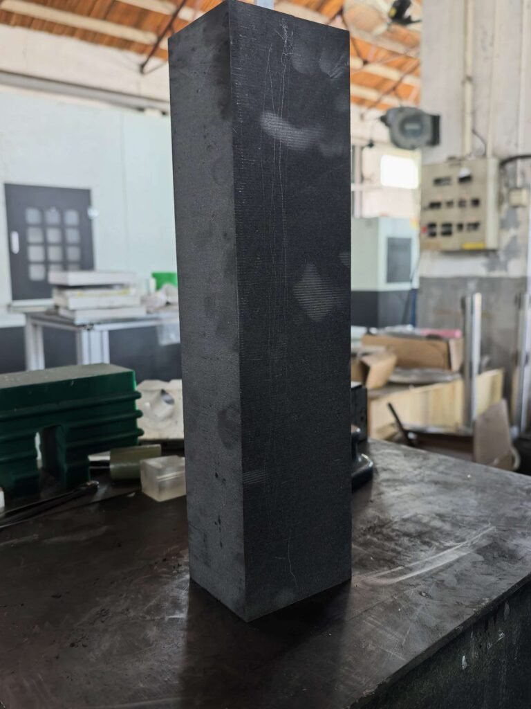
Le published graphite bar trial used an SVI250-80 to produce a nominal 500 × 87 × 70 mm blank. It recorded 0.8 mm wire, 50 m/s wire speed and 42 mm/min feed with wire-diameter compensation off.
Width increased from 87.00 to 87.30 mm, while thickness ranged from 69.90 to 70.10 mm. That width taper is a documented shortcoming relevant to downstream stock planning. It prevents the result being summarized responsibly as one generic precision number.
The test did not qualify thin repeated plates, a complex contour or the minimum internal radius. Its measured dimensions are useful evidence for the blank it produced; transferring them to another geometry would change the claim.
For graphite block cutting vs slicing, request the evidence appropriate to the selected output. A photographed bar cannot stand in for a plate-thickness distribution, and a plate-thickness report cannot prove an internal contour.
Compare Accepted Output and Downstream Work
Build a route sheet containing setup, cutting, repositioning, inspection, finishing and expected material categories. Keep the figures attached to the stage they describe. Otherwise the same kerf or allowance may be counted twice.
For block preparation, record accepted blanks and usable remnants. For slicing, record accepted plates and their thickness condition. For profiling, distinguish a separated outline from a contour that passes its drawing requirements.
Use comparable inspection rules. NIST discusses variability in the measurement process. A route comparison should therefore identify any change in gauge, support or evaluation method rather than interpreting every reading difference as a process improvement.
Do not assume a lower kerf automatically gives a lower delivered-part cost. Stock that later requires more correction can consume that advantage. Compare the whole route using measured output and realistic next-operation requirements.
A Practical Selection Sequence
First, classify the required intermediate output: section, plate or contour. Second, identify the datum and surfaces needed by the next operation. Third, check whether the proposed equipment can reach and support the required geometry.
Then define the acceptance sheet before requesting a trial. Include the feature that determines feasibility, not only convenient dimensions. If the job needs both a thin plate and a difficult outline, retain both requirements in the sample plan.
Finally, compare candidate routes at the same delivery point. Ask which operations are included, what remains to be machined and how nonconforming output is recorded. That’s where an apparently simple graphite block cutting vs slicing decision becomes a credible production choice.
Known Limitations / Trade-offs
No single route is best for all graphite grades, stock sizes and drawings. A convenient starting blank may cost more material; a tightly nested layout may complicate support; a plate-first sequence may improve one setup while making another more fragile.
This comparison does not establish minimum plate thickness, guaranteed contour tolerance or a production rate. Those require configuration-specific documentation and representative tests. Keep provisional cycle-time estimates separate from measured cutting records.
The operations also have different evidence needs. A first sample establishes limited feasibility. Repeated output, changing wire condition and routine repositioning require a broader qualification before a supplier can make a production claim.
Buyer Questions
Can one machine perform all three operations?
Possibly, depending on its configuration and the geometry. Confirm the actual operations, fixtures and access arrangements. A machine name or axis count alone does not define a complete manufacturing route.
Should profiling always follow slicing?
No. Review the workpiece support, thickness, access and downstream requirements for both sequences. The selected route should explain how it preserves the critical features, rather than relying on a universal order of operations.
What should a comparison quotation include?
Give suppliers the same material, stock size, finished requirement, intermediate allowance and quantity. Require an explicit boundary between as-cut and finished output, plus the measurement method and operations included. This makes graphite block cutting vs slicing a comparison of useful deliverables.
Send the drawing and proposed route through our process-review contact page. Mark whether the immediate requirement is a blank, a plate or a contour.