Graphite electrode surface quality is not a finishing concern — it is a cutting outcome. By the time an electrode reaches the EDM machine, its surface state has already been set by the cutting process that produced the blank. Finishing operations can refine what cutting delivers, but they cannot fundamentally reverse damage that originates at the grain level during the first cut.
Understanding what graphite electrode surface quality actually consists of, how the cutting process determines it, and how surface condition cascades through mold quality and production yield is essential for manufacturers who want consistent EDM results without absorbing the cost of secondary recovery processes.
What Defines Graphite Electrode Surface Quality
Graphite electrode surface quality is not a single measurement — it is a composite of three distinct properties that each affect EDM in different ways and at different stages of the electrode’s service life.
Surface roughness describes the macro-texture of the cut face. It is typically measured as Ra (arithmetic mean roughness) or Rz (mean peak-to-valley height). For EDM electrodes, the target Ra after cutting is typically below 1.6 μm; finishing operations are expected to bring this further toward 0.4–0.8 μm depending on the application. An electrode that arrives from cutting with Ra above 3 μm forces finishing to do remedial work rather than precision refinement.
Edge integrity describes the condition of cut edges and corners — the features most exposed to discharge concentration during EDM. Edge chipping, rounding, or micro-burring disrupts the geometry that the electrode is designed to produce in the workpiece. Even chipping below 0.1 mm at a critical corner can affect EDM discharge behavior at that location.
Subsurface defect state is the least visible and most consequential dimension of graphite electrode surface quality. Microcracks, stress concentrations, and contamination embedded beneath the visible cut surface do not affect initial appearance or even early EDM performance. They become failure mechanisms as electrode wear progresses and exposes the damaged subsurface layer, accelerating wear rate at an unpredictable stage in the electrode’s service life.
These three properties are not equally addressable after the fact. Surface roughness is the most recoverable through post-cutting operations. Edge integrity is partially recoverable through careful hand dressing. Subsurface defect state is largely not recoverable — it can only be avoided at the cutting stage.
How the Cutting Method Determines Surface State
The cutting method determines graphite electrode surface quality before any finishing process is applied. Different cutting approaches produce fundamentally different surface states because they interact with graphite’s grain structure in different ways.
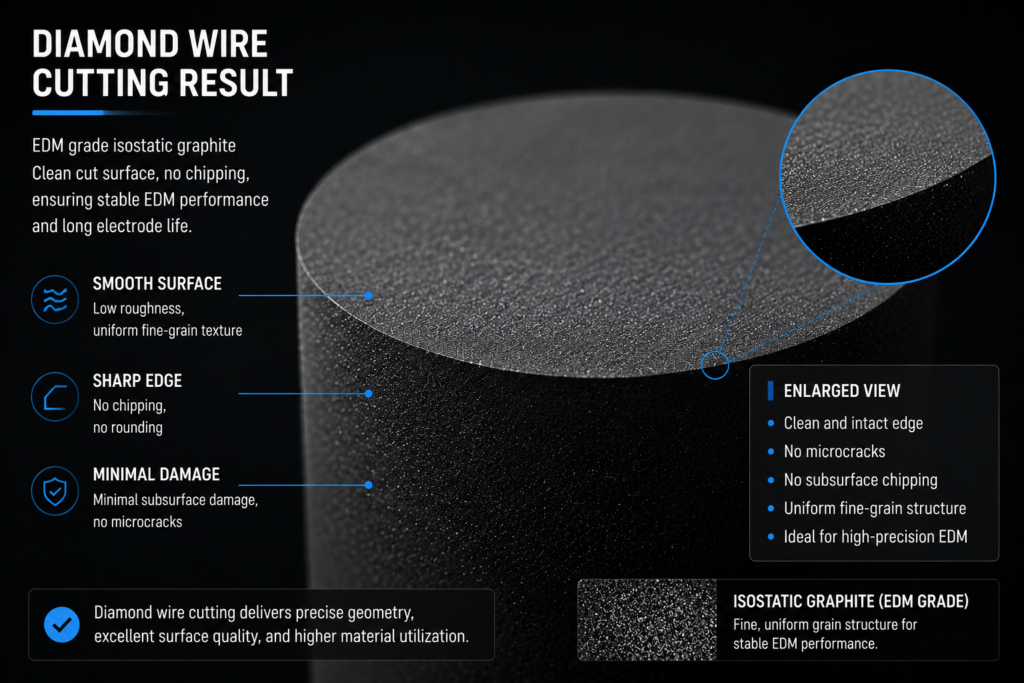
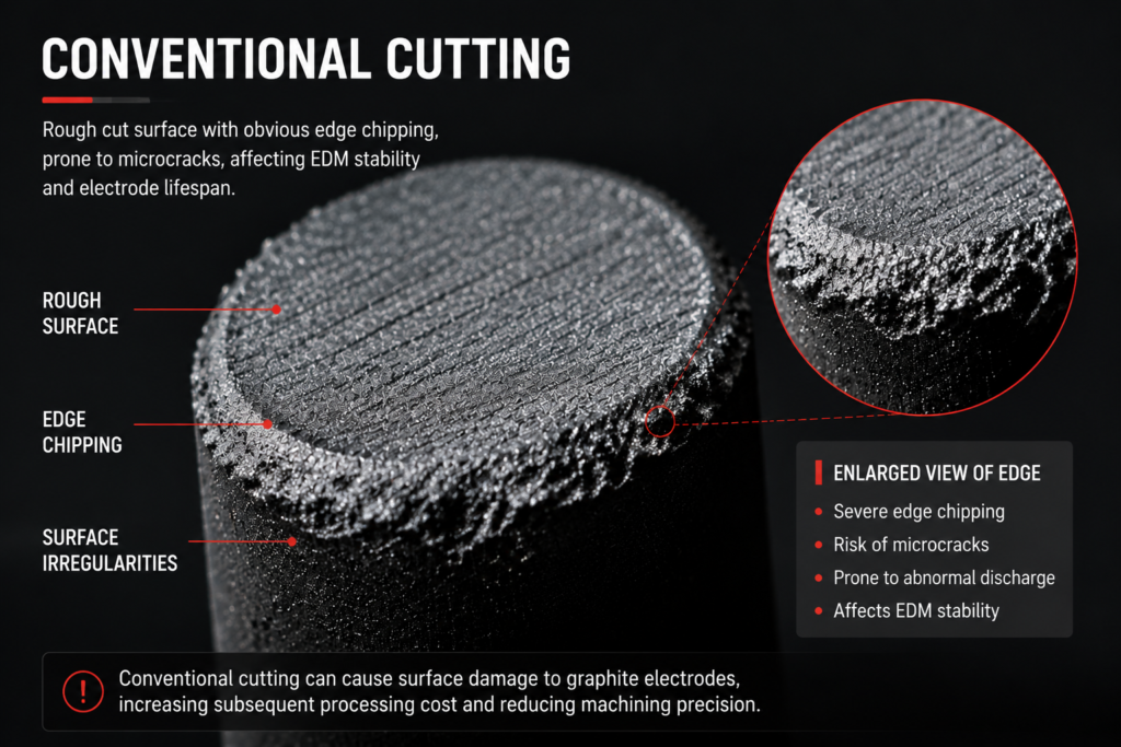
EDM-grade isostatic graphite — the grade most commonly used for precision electrodes, as specified by manufacturers such as SGL Carbon そして Toyo Tanso — has a fine, uniform grain structure that supports sharp edges and smooth surfaces when cut correctly. When cut incorrectly, the same grain structure fractures at grain boundaries, producing chipping, torn surface texture, and a subsurface damage layer where crack tips arrest within the grain structure rather than propagating through.
The table below compares how different cutting approaches affect each dimension of graphite electrode surface quality:
| Surface Property | ワイヤーカット | CNCフライス加工 | Abrasive Disc |
|---|---|---|---|
| Cut face Ra | Low, consistent | Moderate, tool-dependent | Variable, high scatter |
| Edge chipping risk | 低い | 中~高 | 高い |
| Subsurface damage depth | 最小限 | 0.05–0.2 mm (tool-contact-dependent) | 0.1–0.3 mm |
| Surface contamination | Low (water-based coolant) | Moderate (oil mist, chip redeposition) | High (abrasive embedment) |
| Consistency across batch | 高い | Degrades with tool wear | 可変 |
The key differentiator is contact mechanics. CNC milling applies compressive and shear forces through a rotating tool that contacts the graphite repeatedly across the cut path. Each contact cycle applies load to the grain structure. In a material with low fracture toughness, cumulative contact loading produces a zone of stress accumulation beneath the surface — the subsurface damage layer — that is not visible on the cut face but is structurally present.
Wire cutting separates material through a moving abrasive wire under controlled tension and coolant flow. The cutting zone is narrow, the contact force on the graphite is low and distributed, and the process does not apply the compressive loading that produces subsurface grain fracture. The result is a cleaner surface state — lower Ra, better edge integrity, and a shallower subsurface damage layer — before any finishing step is applied.
The relationship between cutting method and surface state is examined in the context of グラファイト電極の切断要件, which covers why surface quality is one of the five non-negotiable demands that the cutting process must meet for reliable EDM electrode production.
Surface Defects and EDM Discharge Stability
Graphite electrode surface quality translates directly into EDM discharge behavior. Each type of surface defect has a specific mechanism by which it disrupts the EDM process, and each disruption has a cost in accuracy, electrode life, or workpiece quality.
Edge micro-burrs and chipping affect discharge initiation. EDM discharge preferentially initiates at sharp geometric features where the electric field is concentrated. When edge chipping or micro-burring alters the designed edge geometry, the discharge pattern shifts away from the designed initiation points. The result is inconsistent spark distribution, reduced process control, and workpiece geometry that deviates from the electrode form.
Surface microcracks affect electrode wear rate and wear consistency. Under EDM thermal cycling, the electrode surface is exposed to repeated heating and quenching at the discharge location. A sound electrode surface with minimal cutting damage accommodates this cycling with predictable, controlled wear. An electrode with pre-existing microcracks — originating from the cutting stage — provides existing crack tips that thermal cycling extends. Wear accelerates at these sites, producing irregular electrode recession and geometry change that cannot be predicted from the electrode’s initial condition.
Surface contamination affects discharge quality throughout the electrode’s service life. Abrasive particles embedded during cutting, oil residue from machining coolants, or graphite dust redeposited on the cut face all introduce foreign material at the discharge surface. This material disrupts the discharge layer, increases arc instability, and contributes to noise in EDM process signals. The key challenges in EDM graphite electrode cutting include surface contamination as a systematic issue in cutting processes that rely on abrasive contact and oil-based cooling.
Residual stress from cutting affects long-term dimensional stability. An electrode that carries significant residual stress from the cutting process will relieve that stress gradually under the thermal cycling of EDM operation. Stress relief manifests as slow dimensional change — the electrode geometry shifts slightly over the course of a production run, independent of intentional wear, introducing error that accumulates across a batch of workpieces.
Graphite Electrode Surface Quality and Its Impact on Mold Production Yield
The consequences of graphite electrode surface quality do not stop at the electrode itself. They cascade forward through the EDM process into mold cavity geometry, then into the products produced from those molds.
The cascade works as follows:
- Electrode surface defects → 放電挙動の不整合 → 加工ワーク表面のばらつき
- 加工ワーク表面のばらつき → 金型キャビティ形状誤差 → 表面仕上げが仕様を下回る
- 金型キャビティ誤差 → 製品寸法偏差 → 部品不良または手直し
- 部品不良 → スクラップコスト、手直しコスト、納期遅延
この連鎖の各ステップは、元の欠陥を増幅します。電極のエッジにある微小なバリが、加工ワークの除去に0.05 mmの不整合を引き起こす場合、それは金型キャビティで0.03 mmの寸法誤差につながる可能性があります。そしてそれは、ツールが修理されるまで、その金型から実行されるすべての部品に表面の欠陥やパーティングラインの不一致を生じさせる可能性があります。.
経済的な意味合いは、グラファイト電極の表面品質は電極レベルでは価格設定されないということです。それは金型レベル、そして最終的には生産実行レベルで価格設定されます。切削コストが低い電極でも、表面が損なわれた場合、切削段階での節約よりも、下流の結果として大幅にコストがかかる可能性があります。.
この連鎖効果により、上流の表面品質への投資(適切な切削プロセスの選択による)は、下流の手直しや二次仕上げへの投資よりも一貫して優れたリターンを示すのです。切削段階で表面の欠陥を防ぐことは、切削プロセスがすでに能力を持っている場合、追加コストはかかりません。下流で表面の欠陥から回復するには、追加の作業、追加のサイクルタイム、そして場合によっては、加工ワークが完了する前に電極の交換が必要になります。.
切削経済性と電極材料効率の関係は、 グラファイト電極のカーフ損失, で検討されています。これは、切削プロセスが材料の無駄と全体の電極生産コストの両方にどのように影響するかをカバーしています。.
切削後の仕上げではなぜ不十分な表面状態を完全に回復できないのか
二次仕上げ作業(ラップ、手仕上げ、表面研削)は、電極生産の標準的な部分です。しかし、それらは、グラファイト電極の表面品質が切削段階で達成されなかった場合の、切削品質の信頼できる代替手段ではありません。.
限界は構造的なものです。仕上げ作業は外表面から内側に向かって機能します。それらはRaを低減し、目に見える粗さを滑らかにし、アクセス可能なエッジを整えることができます。それらは、仕上げ可能な深さの下にある、表面下の損傷には到達できません。0.15 mmの表面下のマイクロクラック層を持つ電極は、視覚的にきれいなRa 0.6 μmに仕上げることができます。それでも、仕上げの深さがクラックの前面に到達しなかったために、EDM中の摩耗を加速する構造的損傷を運ぶ可能性があります。.
エッジの欠けは、欠けが小さく、クリティカルでない特徴にある場合、部分的に回復可能です。電極の設計された形状を定義する鋭いコーナーや薄いリブでは、欠けを回復するために材料を追加することはできません。電極は、損なわれたエッジで使用されるか、拒否されて再切削されます。.
研磨切削プロセスからの表面汚染(埋め込まれた研磨粒子、化学的に結合した切削油残留物)は、標準的な洗浄と仕上げでは完全に除去するのが困難です。超音波洗浄は表面汚染を減らすことができますが、攻撃的な研磨切削中に表面の気孔に埋め込まれた粒子は、洗浄プロセスを通過しても持続し、EDM中の放電表面に残る可能性があります。.
実際の結果は、二次仕上げがコストとプロセス時間を追加し、その適用が示唆するよりも少ない回復しかしないということです。切削品質の悪さを補うために二次仕上げに依存する生産プロセスは、二重に支払っています。一度は不十分な切削のために、そして再び回復作業のために。それでも、仕上げでは対処できない表面下の損傷からの高いリスクを受け入れています。.
下流で回復するのではなく、切削段階で表面品質の問題を防ぐことが、精密電極製造業務全体で一貫して見出されることです。 EDM graphite electrode cutting プロセスリソースの詳細によると、切削段階は、材料の状態がまだ分割されていない時点であるため、表面品質を確立するための生産チェーンの中で最も費用対効果の高いポイントです。成形前、仕上げ前、そして下流の決定がなされる前です。.
グラファイト電極の表面品質が電極生産で繰り返し問題となっている場合(EDM性能の不整合、説明のつかない電極摩耗のばらつき、または金型不良率の上昇として現れる)、診断はほとんどの場合、切削プロセスに戻ります。現在のアプローチ方法が何を提供しているか、そしてより高品質な切削表面が実際にはどのように見えるかについて話し合うために、私たちに連絡してください。.