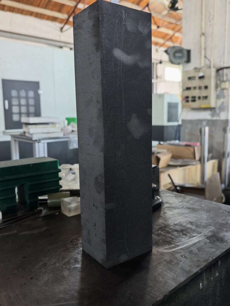
Graphite electrode surface quality is not a finishing concern — it is a cutting outcome. By the time an electrode reaches the EDM machine, its surface state has already been set by the cutting process that produced the blank. Finishing operations can refine what cutting delivers, but they cannot fundamentally reverse damage that originates at the grain level during the first cut.
Understanding what graphite electrode surface quality actually consists of, how the cutting process determines it, and how surface condition cascades through mold quality and production yield is essential for manufacturers who want consistent EDM results without absorbing the cost of secondary recovery processes.
What Defines Graphite Electrode Surface Quality
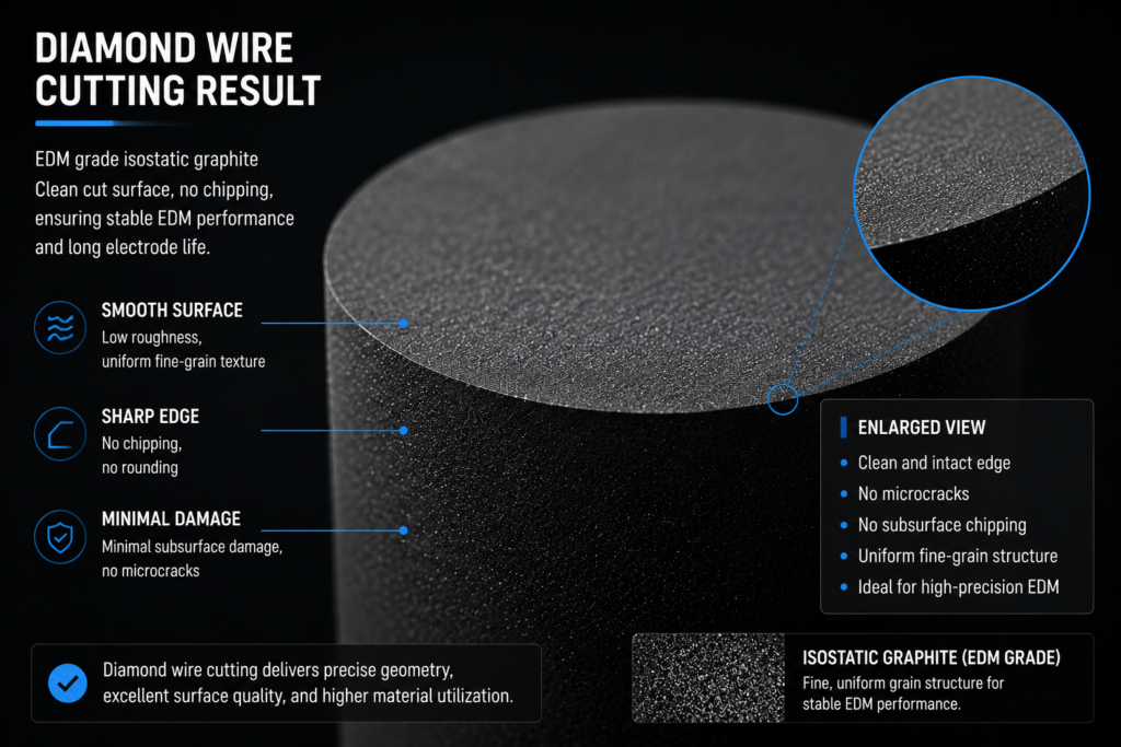
Graphite electrode surface quality is not a single measurement — it is a composite of three distinct properties that each affect EDM in different ways and at different stages of the electrode’s service life.
Surface roughness describes the macro-texture of the cut face. It is typically measured as Ra (arithmetic mean roughness) or Rz (mean peak-to-valley height). For EDM electrodes, the target Ra after cutting is typically below 1.6 μm; finishing operations are expected to bring this further toward 0.4–0.8 μm depending on the application. An electrode that arrives from cutting with Ra above 3 μm forces finishing to do remedial work rather than precision refinement.
Edge integrity describes the condition of cut edges and corners — the features most exposed to discharge concentration during EDM. Edge chipping, rounding, or micro-burring disrupts the geometry that the electrode is designed to produce in the workpiece. Even chipping below 0.1 mm at a critical corner can affect EDM discharge behavior at that location.
Subsurface defect state is the least visible and most consequential dimension of graphite electrode surface quality. Microcracks, stress concentrations, and contamination embedded beneath the visible cut surface do not affect initial appearance or even early EDM performance. They become failure mechanisms as electrode wear progresses and exposes the damaged subsurface layer, accelerating wear rate at an unpredictable stage in the electrode’s service life.
These three properties are not equally addressable after the fact. Surface roughness is the most recoverable through post-cutting operations. Edge integrity is partially recoverable through careful hand dressing. Subsurface defect state is largely not recoverable — it can only be avoided at the cutting stage.
How the Cutting Method Determines Surface State
The cutting method determines graphite electrode surface quality before any finishing process is applied. Different cutting approaches produce fundamentally different surface states because they interact with graphite’s grain structure in different ways.
EDM-grade isostatic graphite — the grade most commonly used for precision electrodes, as specified by manufacturers such as SGL Carbon and Toyo Tanso — has a fine, uniform grain structure that supports sharp edges and smooth surfaces when cut correctly. When cut incorrectly, the same grain structure fractures at grain boundaries, producing chipping, torn surface texture, and a subsurface damage layer where crack tips arrest within the grain structure rather than propagating through.
The table below compares how different cutting approaches affect each dimension of graphite electrode surface quality:
| Surface Property | Wire Cutting | CNC Milling | Abrasive Disc |
|---|---|---|---|
| Cut face Ra | Low, consistent | Moderate, tool-dependent | Variable, high scatter |
| Edge chipping risk | Low | Moderate to high | High |
| Subsurface damage depth | Minimal | 0.05–0.2 mm (tool-contact-dependent) | 0.1–0.3 mm |
| Surface contamination | Low (water-based coolant) | Moderate (oil mist, chip redeposition) | High (abrasive embedment) |
| Consistency across batch | High | Degrades with tool wear | Variable |
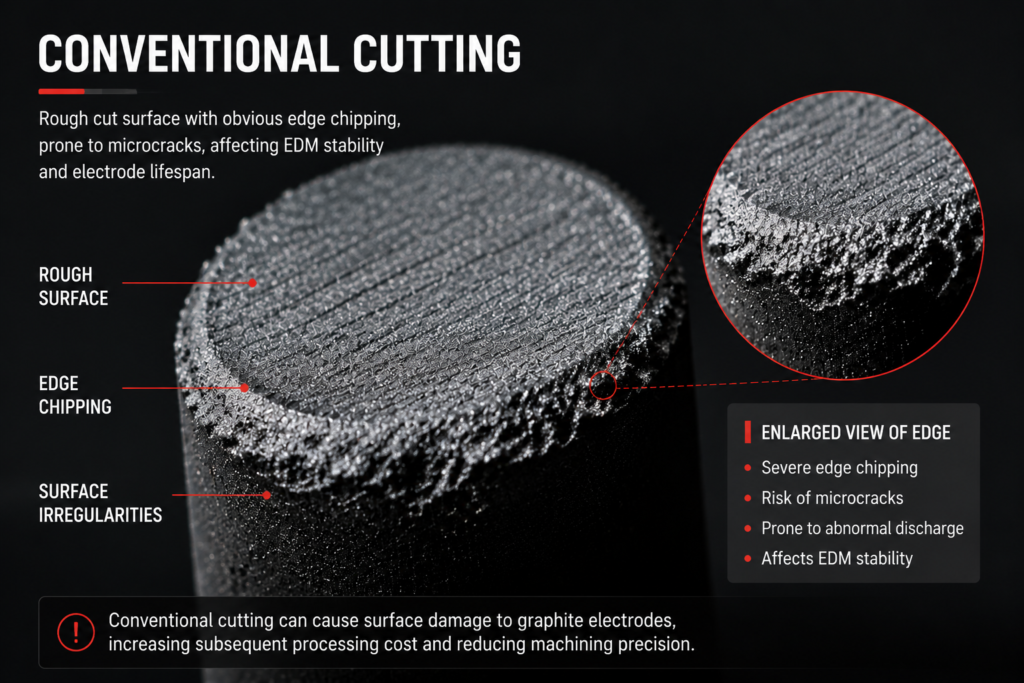
The key differentiator is contact mechanics. CNC milling applies compressive and shear forces through a rotating tool that contacts the graphite repeatedly across the cut path. Each contact cycle applies load to the grain structure. In a material with low fracture toughness, cumulative contact loading produces a zone of stress accumulation beneath the surface — the subsurface damage layer — that is not visible on the cut face but is structurally present.
Wire cutting separates material through a moving abrasive wire under controlled tension and coolant flow. The cutting zone is narrow, the contact force on the graphite is low and distributed, and the process does not apply the compressive loading that produces subsurface grain fracture. The result is a cleaner surface state — lower Ra, better edge integrity, and a shallower subsurface damage layer — before any finishing step is applied.
The relationship between cutting method and surface state is examined in the context of graphite electrode cutting requirements, which covers why surface quality is one of the five non-negotiable demands that the cutting process must meet for reliable EDM electrode production.
Surface Defects and EDM Discharge Stability
Graphite electrode surface quality translates directly into EDM discharge behavior. Each type of surface defect has a specific mechanism by which it disrupts the EDM process, and each disruption has a cost in accuracy, electrode life, or workpiece quality.
Edge micro-burrs and chipping affect discharge initiation. EDM discharge preferentially initiates at sharp geometric features where the electric field is concentrated. When edge chipping or micro-burring alters the designed edge geometry, the discharge pattern shifts away from the designed initiation points. The result is inconsistent spark distribution, reduced process control, and workpiece geometry that deviates from the electrode form.
Surface microcracks affect electrode wear rate and wear consistency. Under EDM thermal cycling, the electrode surface is exposed to repeated heating and quenching at the discharge location. A sound electrode surface with minimal cutting damage accommodates this cycling with predictable, controlled wear. An electrode with pre-existing microcracks — originating from the cutting stage — provides existing crack tips that thermal cycling extends. Wear accelerates at these sites, producing irregular electrode recession and geometry change that cannot be predicted from the electrode’s initial condition.
Surface contamination affects discharge quality throughout the electrode’s service life. Abrasive particles embedded during cutting, oil residue from machining coolants, or graphite dust redeposited on the cut face all introduce foreign material at the discharge surface. This material disrupts the discharge layer, increases arc instability, and contributes to noise in EDM process signals. The key challenges in EDM graphite electrode cutting include surface contamination as a systematic issue in cutting processes that rely on abrasive contact and oil-based cooling.
Residual stress from cutting affects long-term dimensional stability. An electrode that carries significant residual stress from the cutting process will relieve that stress gradually under the thermal cycling of EDM operation. Stress relief manifests as slow dimensional change — the electrode geometry shifts slightly over the course of a production run, independent of intentional wear, introducing error that accumulates across a batch of workpieces.
Graphite Electrode Surface Quality and Its Impact on Mold Production Yield
The consequences of graphite electrode surface quality do not stop at the electrode itself. They cascade forward through the EDM process into mold cavity geometry, then into the products produced from those molds.
The cascade works as follows:
- Electrode surface defects → inconsistent discharge behavior → workpiece surface variation
- Workpiece surface variation → mold cavity geometry errors → surface finish below specification
- Mold cavity errors → product dimensional deviation → part rejection or rework
- Part rejection → scrap cost, rework cost, schedule delay
Each step in this cascade amplifies the original defect. A micro-burr on an electrode edge that causes 0.05 mm of inconsistent workpiece removal may translate into a 0.03 mm dimensional error in the mold cavity — which may then produce surface defects or parting-line mismatch in every part run from that mold until the tool is repaired.
The economic implication is that graphite electrode surface quality is not priced at the electrode level. It is priced at the mold level and ultimately at the production run level. An electrode that cost less to cut but delivered a compromised surface may cost significantly more in downstream consequences than the savings at the cutting stage.
This cascade effect is why investment in upstream surface quality — through appropriate cutting process selection — consistently shows better returns than investment in downstream rework and secondary finishing. Preventing a surface defect at the cutting stage costs nothing extra if the cutting process is already capable. Recovering from a surface defect downstream requires additional operations, additional cycle time, and in some cases, electrode replacement before the workpiece is complete.
The connection between cutting economics and electrode material efficiency is examined in graphite electrode kerf loss, which covers how the cutting process affects both material waste and overall electrode production cost.
Why Post-Cutting Finishing Cannot Fully Recover Poor Surface State
Secondary finishing operations — lapping, hand dressing, surface grinding — are a standard part of electrode production. They are not, however, a reliable substitute for cutting quality when graphite electrode surface quality was not achieved at the cutting stage.
The limitations are structural. Finishing operations work from the outer surface inward: they can reduce Ra, smooth visible roughness, and dress accessible edges. They cannot reach subsurface damage that lies beneath the workable finishing depth. An electrode with a 0.15 mm subsurface microcrack layer can be finished to a visually clean Ra of 0.6 μm — and still carry the structural damage that will accelerate wear during EDM, because the finishing depth did not reach the crack front.
Edge chipping is partially recoverable if the chip is small and on a non-critical feature. On sharp corners or thin ribs that define the electrode’s designed geometry, material cannot be added to recover a chip. The electrode either goes to use with a compromised edge or is rejected and recut.
Surface contamination from abrasive cutting processes — embedded abrasive particles, chemically bonded cutting fluid residue — is difficult to remove completely through standard cleaning and finishing. Ultrasonic cleaning can reduce surface contamination, but particles embedded in surface pores during aggressive abrasive cutting may persist through the cleaning process and remain at the discharge surface during EDM.
The practical outcome is that secondary finishing adds cost, adds process time, and recovers less than its application suggests. A production process that relies on secondary finishing to compensate for poor cutting quality is paying twice — once for the inadequate cut, and again for the recovery operation — while still accepting elevated risk from subsurface damage that finishing cannot address.
Preventing surface quality problems at the cutting stage, rather than recovering from them downstream, is the consistent finding across precision electrode manufacturing operations. As the EDM graphite electrode cutting process resource details, the cutting stage is the most cost-effective point in the production chain to establish surface quality because it is the point where the material’s condition is still undivided — before shaping, before finishing, and before any downstream decisions have been made.
If graphite electrode surface quality is a recurring problem in your electrode production — showing up as inconsistent EDM performance, unexplained electrode wear variation, or elevated mold rejection rates — the diagnosis most often points back to the cutting process. Contact us to discuss what your current cutting method is delivering and what a higher-quality cut surface looks like in practice.