Graphite electrode surface quality is not a finishing concern — it is a cutting outcome. By the time an electrode reaches the EDM machine, its surface state has already been set by the cutting process that produced the blank. Finishing operations can refine what cutting delivers, but they cannot fundamentally reverse damage that originates at the grain level during the first cut.
Understanding what graphite electrode surface quality actually consists of, how the cutting process determines it, and how surface condition cascades through mold quality and production yield is essential for manufacturers who want consistent EDM results without absorbing the cost of secondary recovery processes.
What Defines Graphite Electrode Surface Quality
Graphite electrode surface quality is not a single measurement — it is a composite of three distinct properties that each affect EDM in different ways and at different stages of the electrode’s service life.
Surface roughness describes the macro-texture of the cut face. It is typically measured as Ra (arithmetic mean roughness) or Rz (mean peak-to-valley height). For EDM electrodes, the target Ra after cutting is typically below 1.6 μm; finishing operations are expected to bring this further toward 0.4–0.8 μm depending on the application. An electrode that arrives from cutting with Ra above 3 μm forces finishing to do remedial work rather than precision refinement.
Edge integrity describes the condition of cut edges and corners — the features most exposed to discharge concentration during EDM. Edge chipping, rounding, or micro-burring disrupts the geometry that the electrode is designed to produce in the workpiece. Even chipping below 0.1 mm at a critical corner can affect EDM discharge behavior at that location.
Subsurface defect state is the least visible and most consequential dimension of graphite electrode surface quality. Microcracks, stress concentrations, and contamination embedded beneath the visible cut surface do not affect initial appearance or even early EDM performance. They become failure mechanisms as electrode wear progresses and exposes the damaged subsurface layer, accelerating wear rate at an unpredictable stage in the electrode’s service life.
These three properties are not equally addressable after the fact. Surface roughness is the most recoverable through post-cutting operations. Edge integrity is partially recoverable through careful hand dressing. Subsurface defect state is largely not recoverable — it can only be avoided at the cutting stage.
How the Cutting Method Determines Surface State
The cutting method determines graphite electrode surface quality before any finishing process is applied. Different cutting approaches produce fundamentally different surface states because they interact with graphite’s grain structure in different ways.
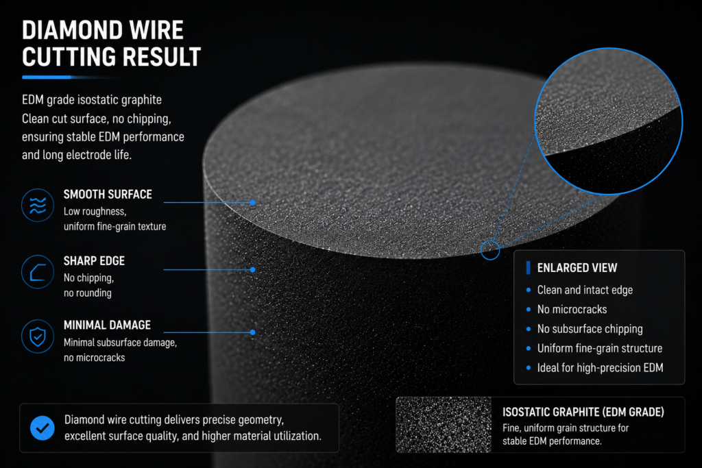
EDM-grade isostatic graphite — the grade most commonly used for precision electrodes, as specified by manufacturers such as SGL Carbon и Toyo Tanso — has a fine, uniform grain structure that supports sharp edges and smooth surfaces when cut correctly. When cut incorrectly, the same grain structure fractures at grain boundaries, producing chipping, torn surface texture, and a subsurface damage layer where crack tips arrest within the grain structure rather than propagating through.
The table below compares how different cutting approaches affect each dimension of graphite electrode surface quality:
| Surface Property | Резка проволоки | Фрезерование на станках с ЧПУ | Abrasive Disc |
|---|---|---|---|
| Cut face Ra | Low, consistent | Moderate, tool-dependent | Variable, high scatter |
| Edge chipping risk | Низкий | От умеренного до высокого | Высокий |
| Subsurface damage depth | Минимум | 0.05–0.2 mm (tool-contact-dependent) | 0.1–0.3 mm |
| Surface contamination | Low (water-based coolant) | Moderate (oil mist, chip redeposition) | High (abrasive embedment) |
| Consistency across batch | Высокий | Degrades with tool wear | Переменная |
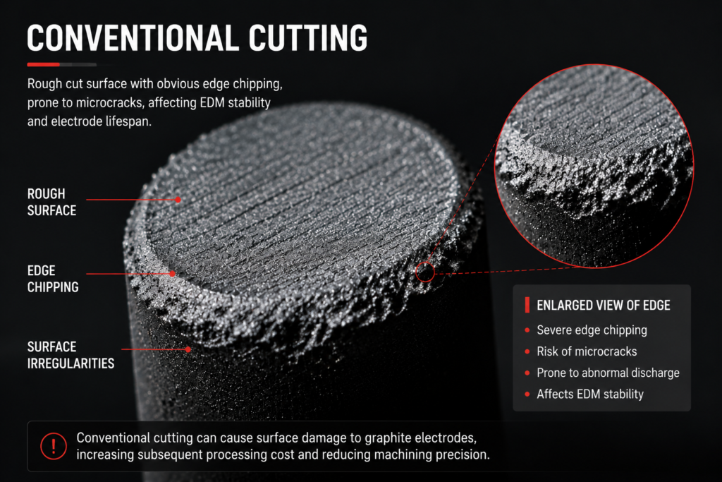
The key differentiator is contact mechanics. CNC milling applies compressive and shear forces through a rotating tool that contacts the graphite repeatedly across the cut path. Each contact cycle applies load to the grain structure. In a material with low fracture toughness, cumulative contact loading produces a zone of stress accumulation beneath the surface — the subsurface damage layer — that is not visible on the cut face but is structurally present.
Wire cutting separates material through a moving abrasive wire under controlled tension and coolant flow. The cutting zone is narrow, the contact force on the graphite is low and distributed, and the process does not apply the compressive loading that produces subsurface grain fracture. The result is a cleaner surface state — lower Ra, better edge integrity, and a shallower subsurface damage layer — before any finishing step is applied.
The relationship between cutting method and surface state is examined in the context of требования к резке графитовых электродов, which covers why surface quality is one of the five non-negotiable demands that the cutting process must meet for reliable EDM electrode production.
Surface Defects and EDM Discharge Stability
Graphite electrode surface quality translates directly into EDM discharge behavior. Each type of surface defect has a specific mechanism by which it disrupts the EDM process, and each disruption has a cost in accuracy, electrode life, or workpiece quality.
Edge micro-burrs and chipping affect discharge initiation. EDM discharge preferentially initiates at sharp geometric features where the electric field is concentrated. When edge chipping or micro-burring alters the designed edge geometry, the discharge pattern shifts away from the designed initiation points. The result is inconsistent spark distribution, reduced process control, and workpiece geometry that deviates from the electrode form.
Surface microcracks affect electrode wear rate and wear consistency. Under EDM thermal cycling, the electrode surface is exposed to repeated heating and quenching at the discharge location. A sound electrode surface with minimal cutting damage accommodates this cycling with predictable, controlled wear. An electrode with pre-existing microcracks — originating from the cutting stage — provides existing crack tips that thermal cycling extends. Wear accelerates at these sites, producing irregular electrode recession and geometry change that cannot be predicted from the electrode’s initial condition.
Surface contamination affects discharge quality throughout the electrode’s service life. Abrasive particles embedded during cutting, oil residue from machining coolants, or graphite dust redeposited on the cut face all introduce foreign material at the discharge surface. This material disrupts the discharge layer, increases arc instability, and contributes to noise in EDM process signals. The key challenges in EDM graphite electrode cutting include surface contamination as a systematic issue in cutting processes that rely on abrasive contact and oil-based cooling.
Residual stress from cutting affects long-term dimensional stability. An electrode that carries significant residual stress from the cutting process will relieve that stress gradually under the thermal cycling of EDM operation. Stress relief manifests as slow dimensional change — the electrode geometry shifts slightly over the course of a production run, independent of intentional wear, introducing error that accumulates across a batch of workpieces.
Graphite Electrode Surface Quality and Its Impact on Mold Production Yield
The consequences of graphite electrode surface quality do not stop at the electrode itself. They cascade forward through the EDM process into mold cavity geometry, then into the products produced from those molds.
The cascade works as follows:
- Electrode surface defects → непоследовательное поведение разряда → вариация поверхности заготовки
- Вариация поверхности заготовки → ошибки геометрии полости пресс-формы → качество поверхности ниже спецификации
- Ошибки полости пресс-формы → отклонение размеров изделия → отбраковка или переделка детали
- Отбраковка детали → стоимость брака, стоимость переделки, задержка графика
Каждый этап этого каскада усиливает исходный дефект. Микроскопическая заусенца на кромке электрода, вызывающая непоследовательное снятие материала заготовки на 0,05 мм, может привести к отклонению размеров полости пресс-формы на 0,03 мм — что затем может привести к дефектам поверхности или несоответствию линии разъема в каждой детали, изготовленной из этой пресс-формы, до тех пор, пока инструмент не будет отремонтирован.
Экономический смысл заключается в том, что качество поверхности графитового электрода оценивается не на уровне электрода. Оно оценивается на уровне пресс-формы и, в конечном итоге, на уровне производственной партии. Электрод, изготовление которого стоило дешевле, но который обеспечил компромиссное качество поверхности, может стоить значительно дороже из-за последующих последствий, чем экономия на этапе изготовления.
Именно этот каскадный эффект объясняет, почему инвестиции в качество поверхности на начальном этапе — за счет выбора соответствующего процесса резки — последовательно приносят лучшую отдачу, чем инвестиции в последующую переделку и вторичную обработку. Предотвращение дефектов поверхности на этапе резки не требует дополнительных затрат, если процесс резки уже способен обеспечить требуемое качество. Устранение дефектов поверхности на последующих этапах требует дополнительных операций, дополнительного времени цикла и, в некоторых случаях, замены электрода до завершения изготовления заготовки.
Связь между экономикой резки и эффективностью использования материала электрода рассматривается в потери на резке графитового электрода, где описывается, как процесс резки влияет как на отходы материала, так и на общую стоимость производства электрода.
Почему последующая чистовая обработка не может полностью восстановить плохое состояние поверхности
Вторичные операции чистовой обработки — шлифовка, ручная доводка, шлифовка поверхности — являются стандартной частью производства электрода. Однако они не являются надежной заменой качества резки, если качество поверхности графитового электрода не было достигнуто на этапе резки.
Ограничения носят структурный характер. Операции чистовой обработки работают от внешней поверхности внутрь: они могут уменьшить Ra, сгладить видимую шероховатость и обработать доступные кромки. Они не могут устранить подповерхностные повреждения, находящиеся под рабочей глубиной чистовой обработки. Электрод с подповерхностным слоем микротрещин толщиной 0,15 мм может быть обработан до визуально чистого значения Ra 0,6 мкм — и при этом сохранить структурные повреждения, которые ускорят износ во время электроэрозионной обработки, поскольку глубина чистовой обработки не достигла фронта трещины.
Сколы кромок частично поддаются восстановлению, если скол небольшой и находится на некритическом элементе. На острых углах или тонких ребрах, определяющих конструктивную геометрию электрода, материал нельзя добавить для восстановления скола. Электрод либо используется с поврежденной кромкой, либо отбраковывается и изготавливается заново.
Загрязнение поверхности абразивными процессами резки — внедренные абразивные частицы, химически связанные остатки смазочно-охлаждающей жидкости — трудно полностью удалить стандартными методами очистки и чистовой обработки. Ультразвуковая очистка может уменьшить загрязнение поверхности, но частицы, внедренные в поры поверхности во время агрессивной абразивной резки, могут остаться после процесса очистки и присутствовать на поверхности разряда во время электроэрозионной обработки.
Практический результат заключается в том, что вторичная чистовая обработка увеличивает стоимость, увеличивает время процесса и восстанавливает меньше, чем предполагается при ее применении. Производственный процесс, который полагается на вторичную чистовую обработку для компенсации плохого качества резки, платит дважды — один раз за неадекватную резку, и второй раз за операцию восстановления — при этом сохраняя повышенный риск подповерхностных повреждений, которые чистовая обработка не может устранить.
Предотвращение проблем с качеством поверхности на этапе резки, а не их устранение на последующих этапах, является последовательным выводом во всех операциях производства прецизионных электродов. Как показывает Резка графитовых электродов для СЭМ , этап резки является наиболее экономически эффективной точкой производственной цепочки для установления качества поверхности, поскольку именно в этой точке состояние материала еще не разделено — до формовки, до чистовой обработки и до принятия каких-либо последующих решений.
Если качество поверхности графитового электрода является повторяющейся проблемой в вашем производстве электродов — проявляющейся в виде нестабильной работы электроэрозионной обработки, необъяснимых колебаний износа электрода или повышенного процента отбраковки пресс-форм — диагноз чаще всего указывает на процесс резки. Свяжитесь с нами, чтобы обсудить, что обеспечивает ваш текущий метод резки и как выглядит поверхность после высококачественной резки на практике.